Installation instructions, only for experts p. 16/48
5. Electrical connection
ATTENTION!
Damage to the unit
● The sauna control unit may only be used for operating and controlling 3 heat-
ing circuits with a maximum heating capacity of 3.5 kW per heating circuit.
The maximum additional output capacity totals 3.5 kW.
1
2
4
3
5
6
b
7
8
9
a
c
d
e
f
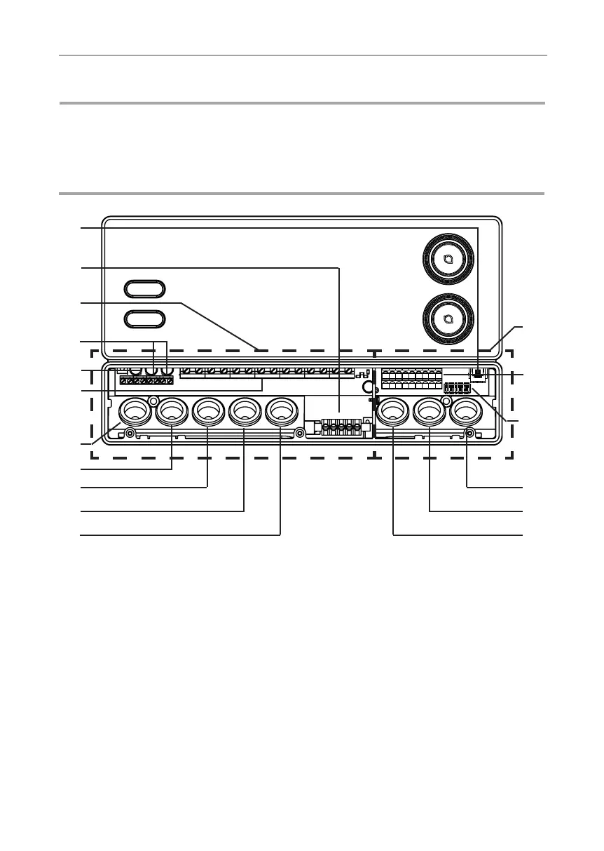
1 Low-voltage connection area
2 Terminal strips for safety shut-off device,
remote start, status output and sensor wires
3 Function selection switch
4 Cable bushing for F2 and foil sensors
5 Cable bushing for F1 sensor and status
output
6 Cable bushing for safety shut-off device
and remote start
7 Cable bushing for additional output
8 Cable bushing for heater wire
9 Cable bushing for power supply cable
a Cable bushing for power booster
b Cable bushing for lights and fan
c Terminal strip for heater and power supply
cable and additional device
d Terminal strip for lights and fan
e Terminal strip for power booster
f Connection area for 230 V / 400 V
g Earth rail
h RJ45 socket for RS-485 and pronet
g
h