Structure and mode of operation
12 A4243-1.0 HBM: public PAD4002A
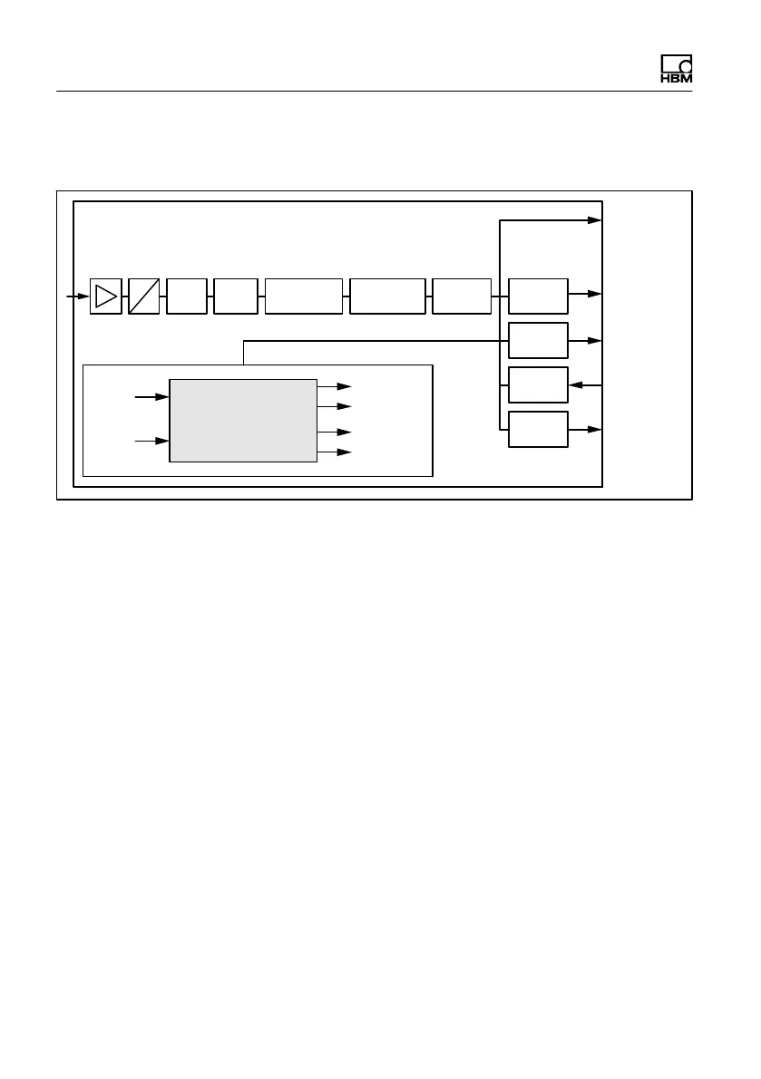
3.2 Signal conditioning
FMD
ASF ICR
SZA
SFA
NOV, RSN
LDW, LWT LIC
PVA
IMD
LIV
TAV, TAS
Net
meas.
value
Gross
meas.
value
Extreme
values
Trigger/
Stop
Limit
values
Samp-
ling
rate
Working
standard
calibration
Filter Tare
A
D
User-defined
scaling
Lineari−
zation
Min/
Max
Trigger
Limit
values
RUN
BRK
Coarse Flow
Fine Flow
Ready
Alarm
Dosing control
Fig. 3.2 Signal conditioning
Digitization is followed by filtering, using digital filters ad
justed by the software. The command ICR changes the
output rate (measured values per second).
In the working standard calibration of the electronics (on
delivery), 0 mV/V corresponds to zero and the maximum
capacity is either 1,000,000digits (NOV≠0), or
5,120,000digits (NOV=0). The two parameters LDW and
LWT give you the opportunity to adapt the characteristic
curve to meet your requirements (scale curve) and you
can use the NOV command to standardize the measured
values to the required scaling value (e.g. 3000d). De
tailed information can be found in the command docu
mentation and in the Online Help for the PanelX pro
gram.
You also have the opportunity to
S switch from gross to net signals,