Structure and mode of operation
PAD4002A A4243-1.0 HBM: public 11
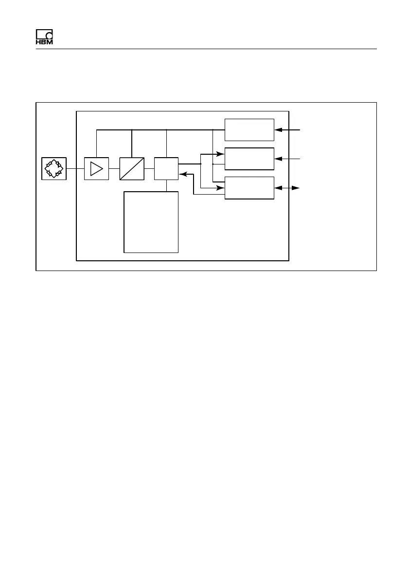
3.1 Structure of the electronics
Voltage
control
Interface
I/Os
Supply
voltage U
B
/GND
Interface
RS-485/CANopen
IO
Trigger,
Stop Dosing
EEPROM
Linearization
Serial number
Digital filter
Data rate
Sensitivity
Zero value
μP
A
D
PAD
Fig. 3.1 Block diagram
The analog transducer signal is first amplified, then ana
log filtered, and digitized in the A/D converter. This signal
is processed in the microprocessor and can be transmit
ted over the interface. Digital inputs/outputs are available
for control. The electronics have various programs for
applications such as filling, dosing, checkweighers or
weight grading machines. All the parameters can be
stored power failsafe.