Interfaces
PAD4002A A4243-1.0 HBM: public 29
7.2 CANopen interface
The interface design follows the CiA DS301 CANopen
standard. The address on delivery is 63.
The CAN bus is set up as a 2‐wire line (CANH and
CANL) (see ISO11898).
Important
You must connect bus termination resistors (each 120W)
at the start and at the end of the bus. The electronics do
not contain a bus termination resistor for CANopen.
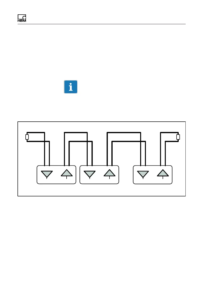
CAN H
CAN L
Master Node 1 Node X
...
120 W120 W
IN
OUT
IN
OUT
IN
OUT
Bus termination Bus termination
Fig. 7.2 CAN bus wiring
Use a cable with a characteristic impedance of approx.
120Ω. HBM cable 1-KAB173 meets these requirements
and also has the same protection class (IP68/69K) as the
PAD housing.
The bus wiring structure was chosen to minimize the
length of the stub lines.