24 CD 2301 Order No. BA 92-12-0231A Issue 05.01.10
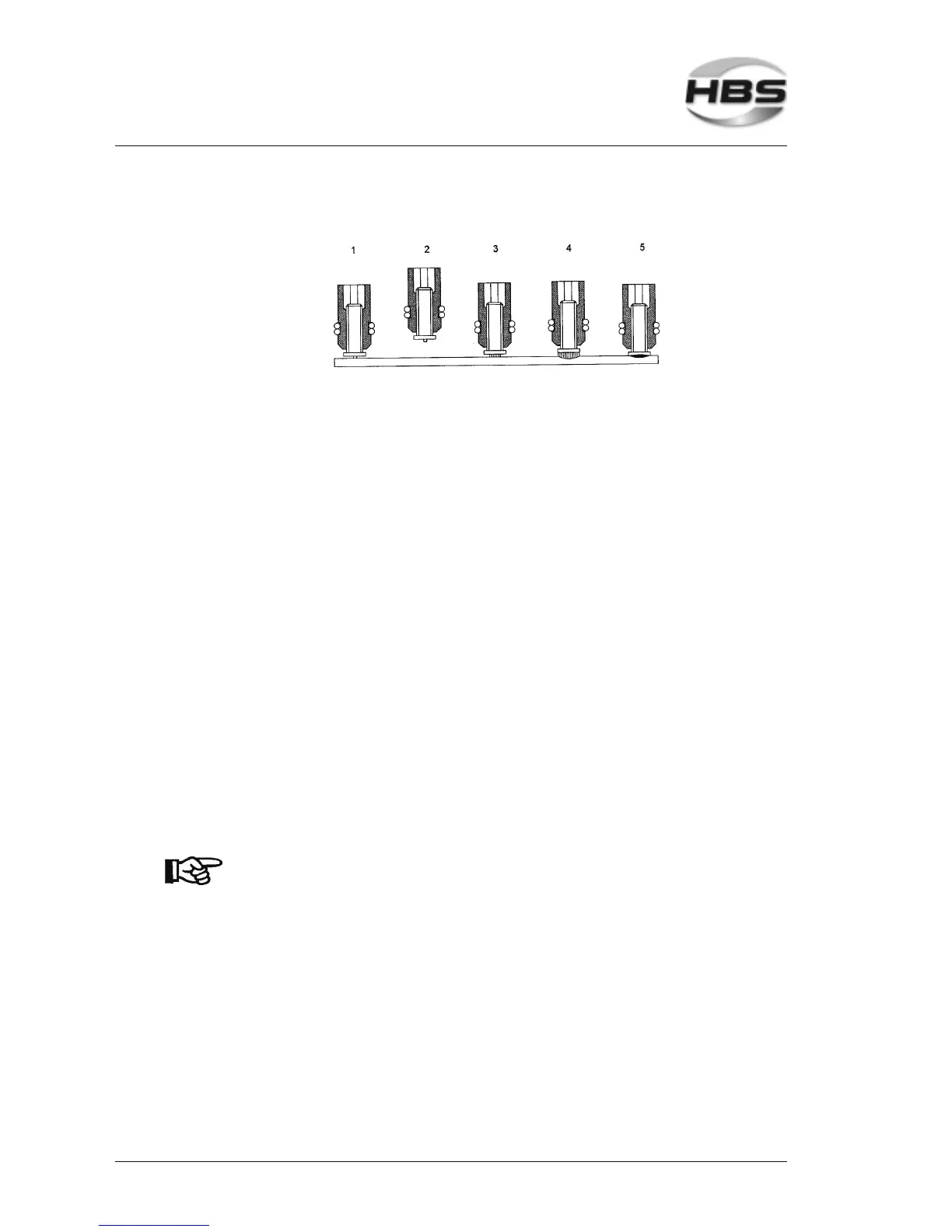
5.2.2 Gap Stud Welding
– The solenoid, which is integrated into the welding gun, lifts the welding element
from the work piece (see figure 5.2.2, position 1) to the adjusted value ”lift” above
the work piece and tensions a pressure spring (see figure 5.2.2, position 2).
– As soon as the welding piston has reached the upper stop, the current to the solenoid
is cut. Simultaneously, the welding thyristor is triggered and releases the current
flow to the welding element.
– The capacitors of the power unit are discharged. Because of the high discharge
current, the ignition tip evaporates explosion-like. The air gap between welding
element and work piece is ionized (see figure 5.2.2, position 3), an arc is produced.
– The arc melts the face of the welding element together with an area of the work piece
of about the same dimension (see figure 5.2.2, position 4).
– The welding element is moved by the pressure spring to the work piece with a speed
of 0,5 to 1,5 m/s. The adjusted spring pressure and the preset lift distance controls
the plunging speed of the welding element.
– Higher plunging speed leads to shortened arc time and consequently to lower
welding energy with identical voltage setting.
– The arc is cut as soon as the welding element touches the work piece.
– Now the capacitors are short-circuited and the rest of the energy drains off (see figure
5.2.2, position 5).
– The pressure spring continues to push the welding element into the weld pool.
– The weld pool solidifies and the welding element is physically connected to the work
piece.
– The time period between ignition of the arc and solidification of the weld pool is about
1 to 2 ms.
With high plunging speed of the welding element, the air gap
closes after vaporization of the ignition tip faster, thus the arc
time becomes shorter. With rapidly oxidizing materials like e.g.
aluminum, the arc must only burn a very short time.
5 Stud Welding Procedure
5.2 Functional Principle of Stud Welding