36 CD 2301 Order No. BA 92-12-0231A Issue 05.01.10
5.10 Welding Elements
The stud welding unit must be suitable for welding the welding elements to be used.
Observe the instructions in the operating manuals.
Welding elements manufactured with the cold formed process have a flange and an
ignition tip (see actual standards in the appendix). During welding, the flange prevents
the arc getting to the cylindric part of the welding element and increases simultaneously
the welding area.
We recommend the following standard welding elements (see appendix).
Use only welding elements of the same lot. Take particular care
not to mix-up different lots. Slightest variations in geometry of
the welding elements, especially of the ignition tip, require
modified settings of the welding process.
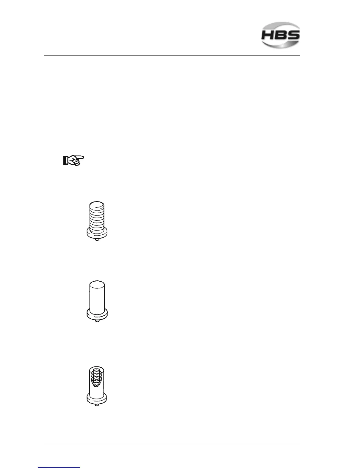
Threaded stud PT * Diameter Length Chuck
M3 6-30 mm 82-50-003
M4 6-40 mm 82-50-004
M5 8-45 mm 82-50-005
M6 8-55 mm 82-50-006
M8 10-55 mm 82-50-008
Materials: Mild steel S235 / St37.3k (4.8) / Stainless steel 1.4301, 1.4303 /
Brass CuZn37 / Aluminum AlMg3
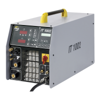
Pin UT * Diameter Length Chuck
3 mm 6-25 mm 82-50-003
4 mm 6-25 mm 82-50-004
5 mm 6-40 mm 82-50-005
6 mm 8-50 mm 82-50-006
7.1 mm 10-55 mm 82-50-071
Materials: Mild steel S235 / St37.3k (4.8) / Stainless steel 1.4301, 1.4303 /
Brass CuZn37 / Aluminum AlMg3
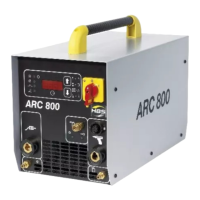
Pin with internal thread IT * Diameter Length Chuck Internal thread
(internal thread insert)
5 mm 6-30 mm 82-50-905 M3
6 mm 8-30 mm 82-50-906 M3
6 mm 8-30 mm 82-50-906 M4
7.1 mm 10-30 mm 82-50-971 M5
8 mm 10-40 mm 82-50-908 M6
Materials: Mild steel S235 / St37.3k (4.8) / Stainless steel 1.4301, 1.4303 /
Brass CuZn37 / Aluminum AlMg3
* above 40 mm length, only weldable with distance ring up to 55 mm,
order no. 92-40-010.
5 Stud Welding Procedure
5.10 Welding Elements