Page
69
Heathkif
Connect the wires at the free
end of
the 8-wire
cable
coming from
the right front corner of the chassis to
the oscillator circuit
board as follows:
(
)
Gray wire
to
hole
10 (S-l).
(
)
Violet wire
to hole 12 (S-l).
(
)
Blue
wire to hole 15 (S-l).
(
)
Green wire to hole 17 (S-l).
(
)
Yellow
wire
to
hole 20 (S-l).
( )
Orange wire to
hole 30 (S-l).
(
)
Red
wire
to
hole
40 (S-l).
(
)
Brown wire to
hole 80 (S-l).
Refer to
Pictorial
3-14
(Illustration
Booklet, Page
31)
for the
following steps.
(
)
Refer to
Detail 3-14A
(Illustration Booklet,
Page
31)
and turn an
additional
6-32
nut onto
each of the
nine screws
extending from the
subchassis (at CF, CG, CH,
CJ,
CK, CL, CN, CP,
and CR). Then
place a #6
lockwasher onto
each
of these
screws.
(
)
Position the oscillator circuit board into the
chassis so the nine screws
extending from the
subchassis pass through the
nine correspond-
ing holes in the circuit board. Then use nine
6-32
nuts to secure the circuit board in place.
(
)
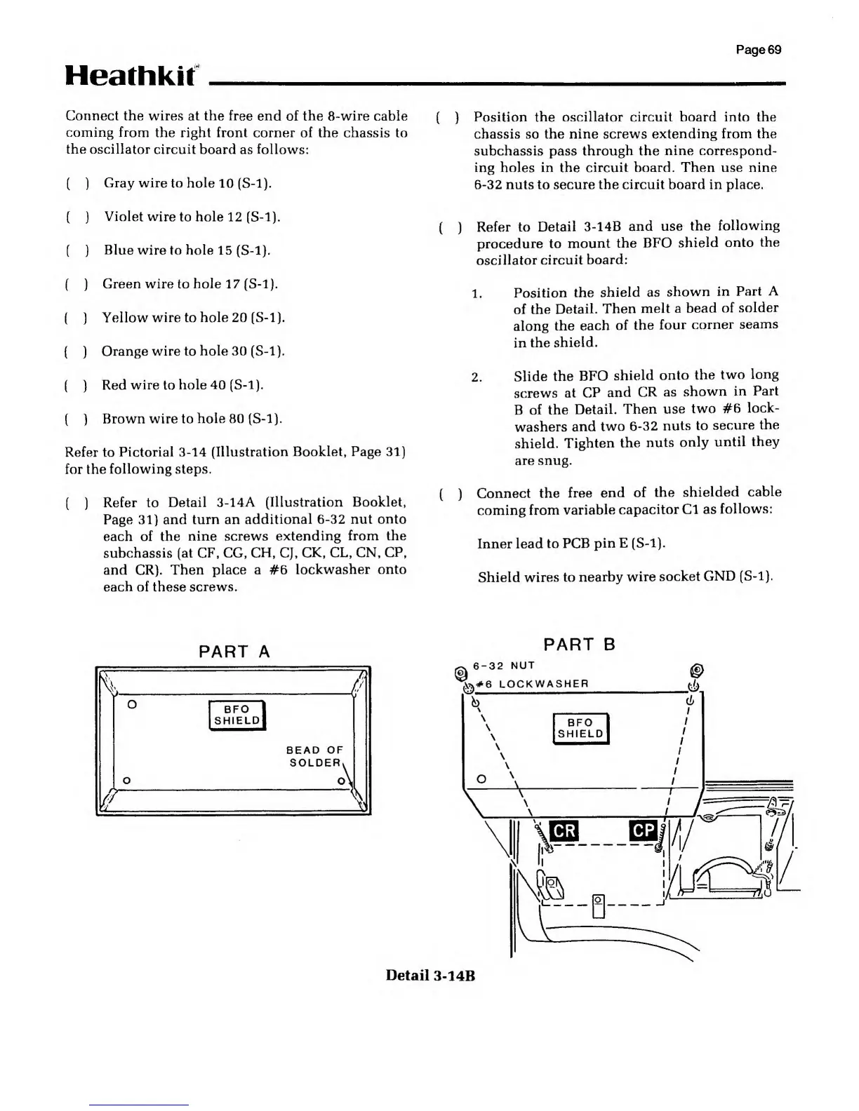
Refer to
Detail 3-14B
and use
the
following
procedure to
mount the
BFO
shield onto
the
oscillator
circuit board:
1.
Position
the
shield as
shown in
Part
A
of the
Detail.
Then
melt
a bead
of
solder
along
the
each
of the
four
corner
seams
in
the
shield.
2.
Slide
the
BFO
shield
onto the
two
long
screws
at
CP
and
CR as
shown
in
Part
B
of the
Detail.
Then use
two #6
lock-
washers
and
two
6-32
nuts to
secure the
shield.
Tighten
the
nuts
only
until
they
are snug.
(
)
Connect the
free
end of the
shielded
cable
coming
from
variable
capacitor Cl as
follows:
Inner lead to
PCB
pin E
(S-l).
Shield
wires to
nearby wire
socket
GND
(S-l).
PART A
PART B
BEAD OF
SOLDER
6-32 NUT
^#6
LOCKWASHER
(4
Detail
3-14B