11
2.1.1 Brake pedal
The installation of brake pedal is suspension type. Specific structure is shown in Figure
2-2. The force acting on the pedal is converted to the brake oil pressure by the push rod of the
brake valve, and the wet disc brake of the driving axle is acted on to realize braking.
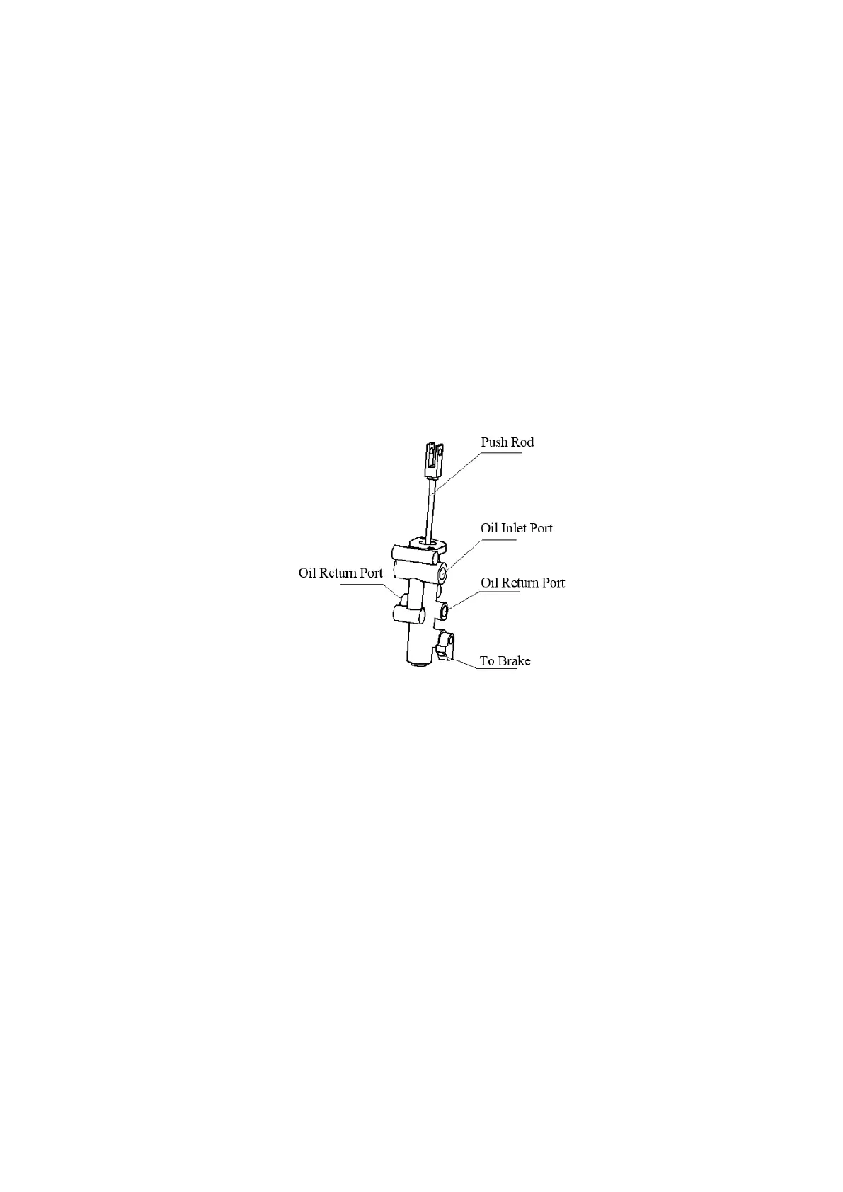
2.1.2 Brake valve
The shape of the brake valve and the position of each interface are shown in Fig. 2-3.
Brake valve mainly consists of seat, safety stem, support, piston, reaction piston, slide
valve and so on.
The main principle of brake valve is introduced in hydraulic system.
Figure 2-3 Shape of the brake valve and the position of each interface
2.1.3 Connection between brake system and drive axle
There are two connections between the brake system and the driving axle, one is the
connection between the brake oil outlet of the vehicle and the other is the connection of the
parking brake cable.
(1)The connection of service brake
The brake hose from the brake valve to the driving axle is connected with the service
brake connection port shown in Figure 2-4 ①. The pre-tightening torque is 12-16Nm. Note:
The bending radius of the brake hose shall be as large as possible to reduce the recovery
resistance when the pedal is loosened.
 Loading...