18
steering system will automatically overflow in order to protect the components of the system
from damage, so as to realize self-protection. The output pressure of the steering gear has
been adjusted according to different models before leaving the factory. The user can not
adjust it by himself to avoid damaging the hydraulic components. The steering system
pressure of the truck is set at 9MPa.
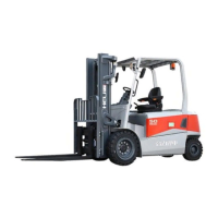
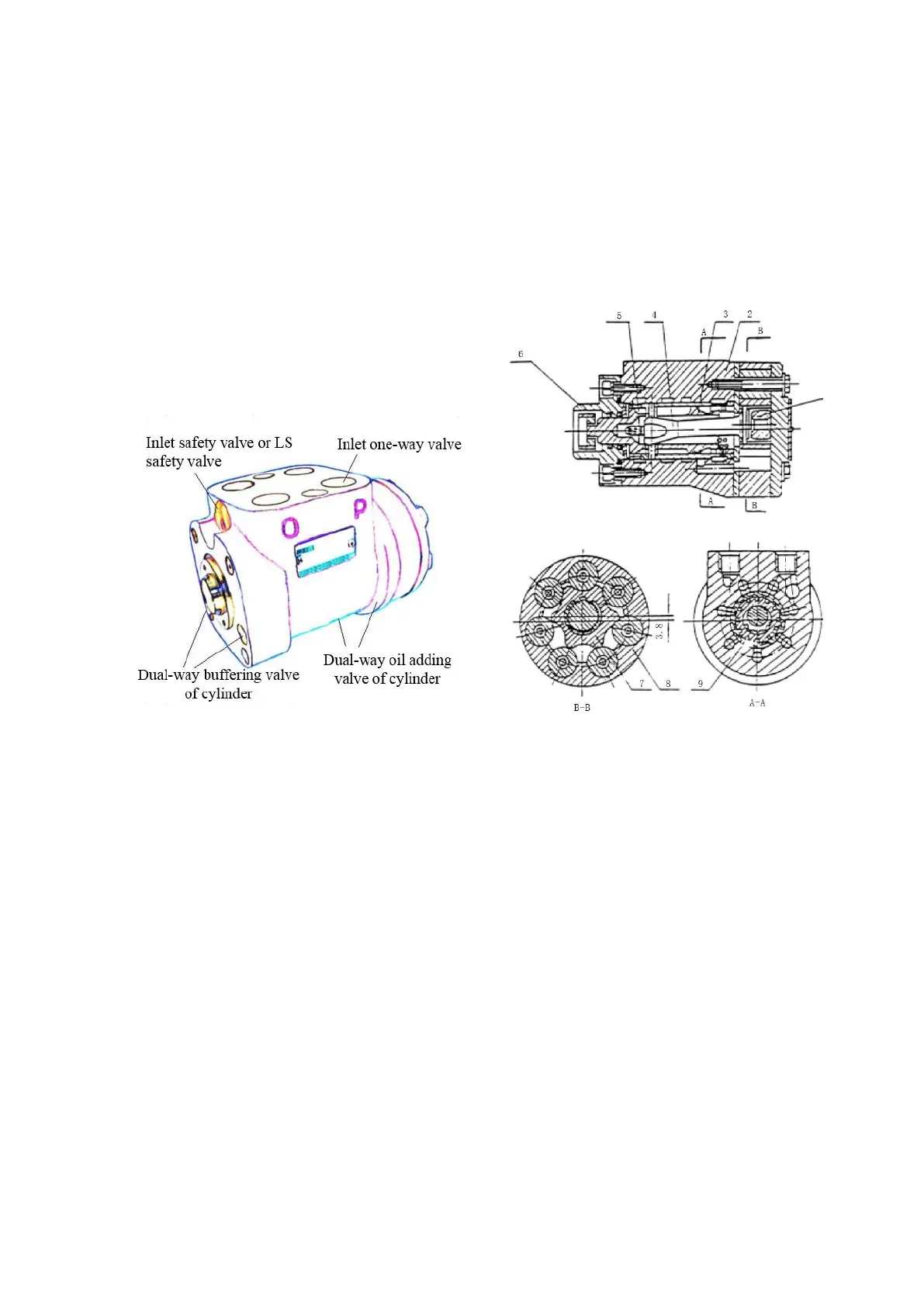
Figure 3-4 full hydraulic steering unit
1.Limit post 2.Valve body 3.Valve core 4.Universal driving shaft
5.Spring 6.Connection block 7.Rotor 8.Stator 9.Valve bush
3.1.5 Steering axle
The steering axle (Fig. 3-5) consists of steering axle body, steering cylinder, connecting
rod, steering knuckle assembly, steering hub and steering wheel. The steering axle drives the
connecting rod motion by moving of steering cylinder’s piston rod. The motion of the
connecting rod drives the steering knuckle assembly to rotate around the main pin connected
to the steering axle, thus realizing the steering. The steering wheel is mounted on the steering
hub, which is connected with the steering knuckle assembly through two tapered roller
bearings. The main pin is matched with the steering axle body through two pin holes on the
upper and lower axle body. The upper and lower radial directions of the main pin are
supported by two self-lubricating axle sleeves installed on the bridge axle. The axial direction
 Loading...