45
•
Park the vehicle on the level surface.
MAIN/SIDE STAND LUBRICATION
•
Check the main/side stand return spring for
damage or loss of tension.
•
Check the main stand (1)/side stand (2)
for freedom of movement.
•
Make sure the side stand is not bent.
•
Lubricate the side stand pivot if necessary.
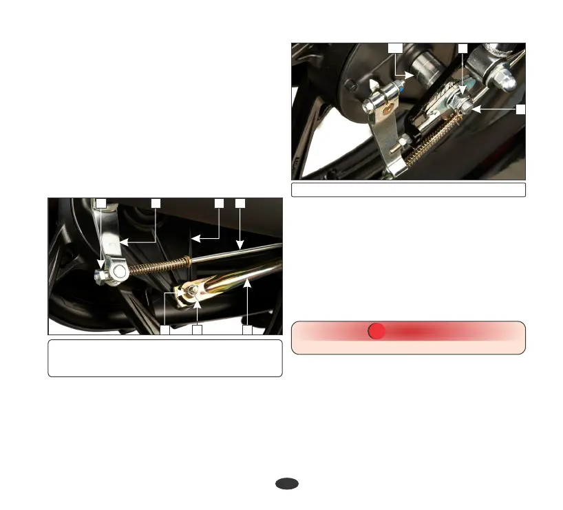
(b) Rear wheel
•
Disconnect the brake stopper arm (4) from
the brake panel (5) by removing split pin
(6) and nut (7).
Removal
•
Support the vehicle securely on the main
stand and raise the rear wheel off the
ground.
•
Remove the rear brake adjusting nut (1)
and disconnect the brake rod (2) from the
brake arm (3) by pushing down the brake
pedal.
•
Remove the rear axle nut (8) and pull out
the rear axle (9) and collar (10).
•
Remove the wheel.
(1) Rear brake adjusting nut (2) Rear brake
rod (3) Brake arm (4) Brake stopper arm
(5) Brake panel (6) Split pin (7) Lock nut
•
After installing the wheel, apply the brake
several times and check for free wheel
rotation when released.
•
Brake stopper arm nut torque: 2.2 kgf-m
Adjust the brake (page 41) and drive chain
(page 37).
•
Reverse the removal procedure
Installation
•
Axle nut torque: 5.4 kgf-m
CAUTION
!!
Always replace used split pins with new ones.
(8) Axle nut (9) Rear axle (10) Collar
1 3 5 2
7 6 4
9
10
8