6/42
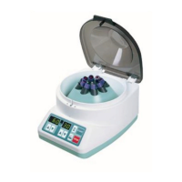
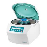
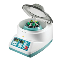
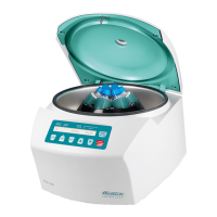
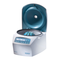
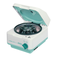
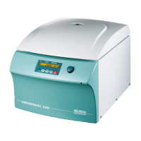
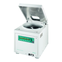
3 Description of the centrifuge
These microprocessor controlled centrifuges mainly consist of the following electrical
components:
• Control panel, microprocessor controlled
• Supply board
• Frequency converter with braking chopper (motor control), microprocessor controlled
• Motor with speed sensor (speedometer) and imbalance switch
• Brake resistor
• Lid lock
3.1 Control panel (A4)
The control panel is the brain or the master of the centrifuge. This MASTER controls its
SLAVE via a serial data bus system. This SLAVE is the following component:
− frequency converter
The control panel carries out the following tasks:
• Managing operator entries and controlling the LCD display
• Saving of 3 run programs
• Controlling the components:
− frequency converter via the release line and the serial interface
• Evaluating the speed sensor (speedometer)
• Evaluating the imbalance switch
• Evaluating the frequency converter error message line
• Evaluating the message line lid lock open/closed
• Triggering the relay for the lid lock solenoid when the rotor has standstill
• Type of serial interface:
− 5 Volt interface with three wires (16-pole flat ribbon cable, pole 6, 8 and 11)
• The voltage supply for the control panel is provided by the supply board via the flat
ribbon cable:
+ 10...15 Volt pole 1, 2
GND pole 15, 16
3.2 Supply board (A1)
The supply board carries out the following tasks:
• Current supply 12 V DC and 5 V DC for the supply board
• Current supply 12 V DC for the control panel
• Slot X5 for message line lid lock open/closed. Transmission of the signal to the
control panel via opto-coupler.
• Voltage supply for the speed sensor (speedometer)
• Slot for speed sensor cable and transmission of the speed pulses to the control
panel and to the frequency converter
• Triggering the relay for the lid lock solenoid when the rotor has standstill
• Slot for imbalance switch and direct transmission of the imbalance signal to the
control panel