31/42
12 Technical documents
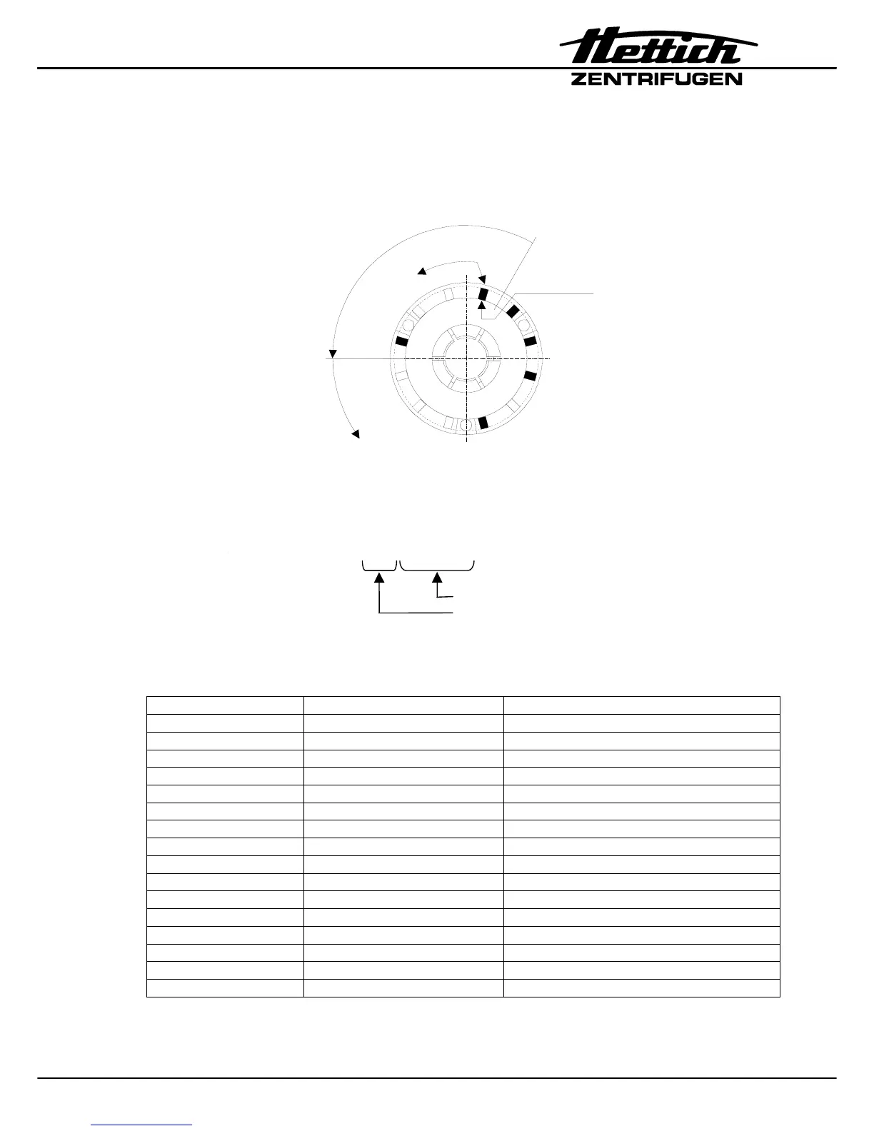
12.1 Tachometer code configuration of the rotors
Example: tachometer code no. 1
tachometer code determines:
1. maximum speed of rotor
2. run up and braking ramps
3. control response of electronics
START-STOP
combination
Information
START
North Pole
Rotor viewed from underneat
e.g. Rotor 1624 1001 00010111
rotor code
Start / Stop combination.
The begin of the Start / Stop combination is
marked with a white dot.
0 = no magnet (empty place), 1 = magnet inserted
Tachometer code-no. Configuration Rotor
0 1001 0000 1111
1 1001 0001 0111 1095
2 1001 0001 1011 1089
3 1001 0001 1101 1416
4 1001 0001 1110 1116
5 1001 0100 0111
6 1001 0101 0101 1030
7 1001 0101 0110 1112
8 1001 0101 1010 1135
9 1001 0110 0011 1450
10 1001 0111 0001 E778
11 1001 1000 0111 1114, 1115, 1118, 1118-01, 1120, 1126
12 1001 1000 1011
13 1001 1000 1101
14 1001 1000 0011 SK 55.92
15 1001 1100 0011
This tacho code can be measured on plug X4 of the tacho sensor B3 ( see also chapter
"Circuit diagrams").