41/42
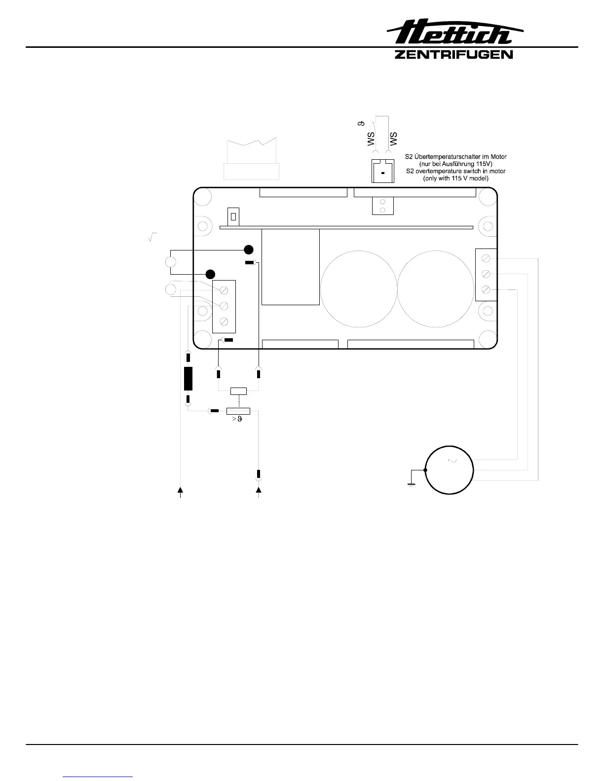
12.2.10 Connecting diagram frequency converter (A2)
W2
V2
U2
S101
Bremswiderstand
brake resistor
S501
S2
P10
+
+
-
P1
-
S102
U
U
DC
YE
RD
BK
N
U1
PE
U
U
AC
A2 Frequenzumrichter/
frequency converter
M1
3
Motor / motor
R1
Übertemperatursicherung für R1
overtemperature fuse for R1
F3
von Versorgungs-
platine A1 X5/Pin 2
from supply board A1
X5/pin 2
von Versorgungs-
platine A1 X5/Pin 4
from supply board A1
X5/pin 4
U = Netzspannung /
mains voltage
AC
U = U x 2
DC AC
zur Versorgungsplatine A1 / X9
to supply board A1 / X9
S501
1
2
S2
>
12
Netzdrossel L1
(nur bei 230 V Ausführung,
)
mains choke coil L1
(only with 230 V model,
from serial no. XXXX-02-00)
ab Werk Nr. XXXX-02-00
L1
Brake resistor (R1):
230 V Version: 330 Ω
115 V Version: 82 Ω
Motor resistance value (M1; cold motor, between 2 wires):
230 V Version: 8.4 Ω
115 V Version: 2.1 Ω