Page 12 of 38 September 2016
EntryProx User Manual, 4045-905, Rev. C.4
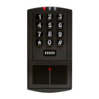
4.3 Controller Keypad Wiring – Standard Installation
In a standard installation, the antenna housing remains installed in the controller keypad, and the
complete unit is installed outside of the secured area. This is appropriate for interior doors or
“low-risk” exterior installations.
CAUTION: For compliance with the UL294 Standard for access control, additional installation
requirements must be met. See Section 4.7: Installation and Compliance for UL 294 .
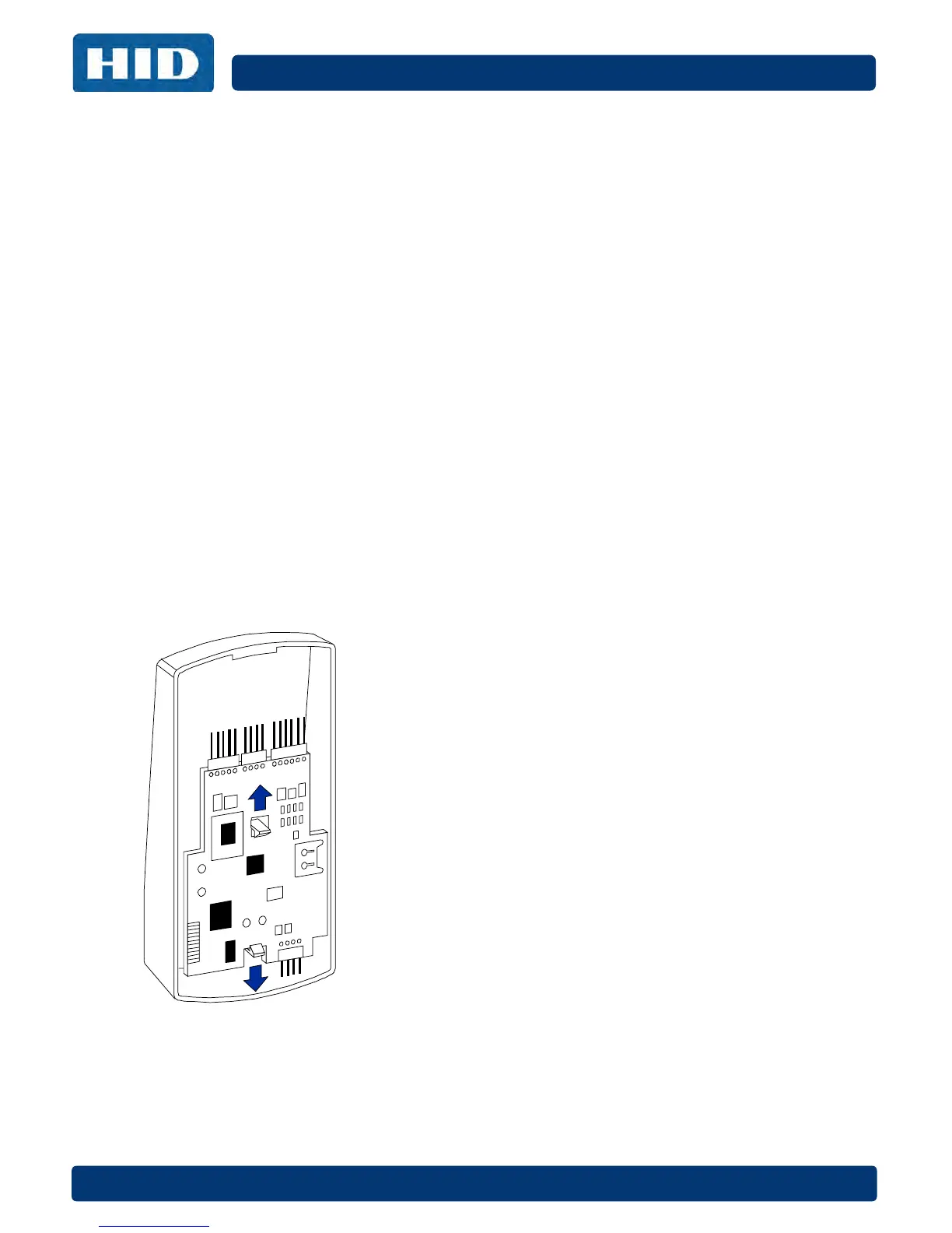
To wire the EntryProx unit for a standard installation, refer to perform these steps, referring to the
following figure for clarification.
1. Touch a grounded object BEFORE touching the main circuit board to guard against
possible static discharges.
2. Remove the main circuit board by pushing outward on the two spring tabs in the direction
shown in the following figure.
3. Lift the main circuit board.
4. Make the wiring connections for the door locking devices, the power supply, and the alarm
inputs and outputs. See Section 5: Wiring for appropriate wiring diagrams.
5. Reattach the main circuit board to the controller keypad unit.
6. Attach the controller keypad unit to the mounted backplate and secure the EntryProx unit
with a hex screw or tamper screw.
CAUTION: A ribbon cable holds the main circuit board to the controller keypad board. DO NOT
CUT OR REMOVE this cable from its connector.
Removing the Circuit Board