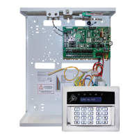
EURO 280 Installation Manual
Page: 2
Contents Page
1. System Overview ......................................................................................................................................................................................................... 3
1.1 System Overview ................................................................................................................................................................................................... 3
1.2 The Devices ............................................................................................................................................................................................................ 4
1.3 EURO 280 Input Mapping Table: ........................................................................................................................................................................... 6
1.4 EURO 280 Output Mapping Table:......................................................................................................................................................................... 7
2. Installation ................................................................................................................................................................................................................... 8
The Printed Circuit Board ................................................................................................................................................................................................. 9
2.3 Technical Specification ........................................................................................................................................................................................ 10
2.1 Important Installation Notes ............................................................................................................................................................................... 11
2.2 Communication ATE Loom .................................................................................................................................................................................. 12
2.3 Battery Connection ........................................................................................................ ...................................................................................... 12
2.4 AC Mains Supply Connection ............................................................................................................................................................................... 12
2.5 Engineer Keypad Connection ............................................................................................................................................................................... 13
3. Input Connections ...................................................................................................................................................................................................... 14
3.1 Default Grade 2 DEOL (Double End of Line) Input Wiring .................................................................................................................................... 15
3.2 Grade 3 Mask/Fault Input Wiring ........................................................................................................................................................................ 15
4. Output (PGM) Connections ........................................................................................................................................................................................ 16
4.1 Negative Applied Wiring ...................................................................................................................................................................................... 16
4.2 Positive Applied Wiring ........................................................................................................................................................................................ 16
5. External Sounder Connections ................................................................................................................................................................................... 17
5.1 Grade 3 External Sounder Wiring ........................................................................................................................................................................ 17
5.2 Grade 2 External Sounder Wiring with a Grade 3 Bell ......................................................................................................................................... 17
5.3 Grade 2 External Sounder Wiring ........................................................................................................................................................................ 18
6. Connecting the EURO Peripherals .............................................................................................................................................................................. 19
6.1 Connecting the LCD Keypad (EURO-LCDPZ) ......................................................................................................................................................... 19
6.2 Connecting the Internal Tag Reader (EURO-PROXI – EUR-107) ........................................................................................................................... 22
6.3 Connecting the External Proximity Reader (EURO-PROXE - EURO-108X) ............................................................................................................ 24
6.4 Connecting the Zone Expander Module (EURO-ZEM8) ....................................................................................................................................... 27
6.5 Connecting the Zone Expander Module with 4 PGMs (EURO-ZEM8+) ................................................................................................................ 30
6.6 Connecting the Zone Expander Module with PSU (EURO-ZEM8+PSU) ................................................................................................................ 34
6.7 Connecting the Enforcer Wireless Zone Expander Module (EURO-ZEM32-WE) .................................................................................................. 38
6.8 Connecting the Output Expander Module (EURO-OEM8R8T) ............................................................................................................................. 40
6.9 Connecting the Output Expander Module with PSU (EURO-OEM16R+PSU) ....................................................................................................... 42
7. The Inovonics Radio Expander ................................................................................................................................................................................... 44
7.1 The Inovonics Radio Expander ............................................................................................................................................................................. 44
7.2 The Inovonics Radio PIR ....................................................................................................................................................................................... 44
7.3 Addressing the Radio Expander ........................................................................................................................................................................... 44
7.4 Assigning Radio Detectors ................................................................................................................................................................................... 45
7.5 Deleting Radio Detectors ..................................................................................................................................................................................... 45
7.6 Display the Signal Strength .................................................................................................................................................................................. 45
7.7 Assigning Repeaters to the Expander .................................................................................................................................................................. 45
7.8 Supervision Time ................................................................................................................................................................................................. 45
7.9 Problem Solving ................................................................................................................................................................................................... 46
7.10 Technical Specification ...................................................................................................................................................................................... 46
8. The PSTN Modem ...................................................................................................................................................................................................... 47
9. The RS232 Module ..................................................................................................................................................................................................... 49
9.1 Connecting to the Upload/Download Software .................................................................................................................................................. 50
10. Access Levels ............................................................................................................................................................................................................ 51
Default User Code: 1234
Default Master Manager: 2222
Default Engineer Code: 1111
 Loading...
