Page: 9
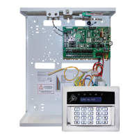
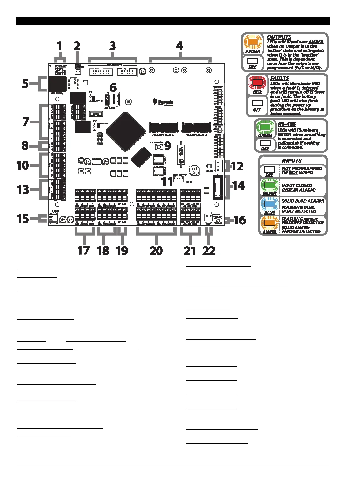
The Printed Circuit Board
1] Ethernet Status LEDs
2] Case Tamper
Connect the tamper switch cable here or use a jumper for Hold-off.
3] ATE Outputs
Connects the supplied communication loom to enable an additional 9
programmable outputs. These are low current and would normally be used
to connect a stand-alone communicator to the panel. See page: 12.
4] Modem Slots 1 & 2
Communications modules are inserted here. See page: 47
5] Ethernet (LAN)
(For future use – DO NOT USE)
6] Micro-SD Card Slot (For future use – DO NOT USE)
7] Output Connections
Output connection terminals (1- 6) see page:
8] Auxiliary 12V power supply
9] E-Fuse Reset Switch
Press to reset the switchable input / output / peripheral fuses once the
issue has been resolved.
10] External Sounder Connection
11] Engineer Keypad
An addressed keypad can be connected here to allow access to the
engineer menu. See page: 13.
12] 0V & 17V connection
Connects the 0V and 17V supply from the power supply
transformer (DC-IN).
13] Microphone & Speaker Connection
For future use
14] Battery Fuse
15] USB Connection
This connection is used to connect to a PC to allow uploading and
downloading of data using the InSite software (see page: 50).
16] Battery connect switch
Press to power up the control panel without the mains supply
connected. See page: 12.
17] Input Terminals
2 x Input terminals (block 1 and block 5)
18] Input Terminals
2 x Input terminals (block 2 and block 6)
19] 12V Power rails
2 x 12V Power rails
20] Input Terminals
4 x Input terminals (blocks 3, 4, 7 and 8)
21] 2 x RS485 bus terminals
Connects peripherals. See from page: 4.
22] Battery connection:
See page: 12.
 Loading...