Installation MS20/MS30
Release
11
07/2013
19
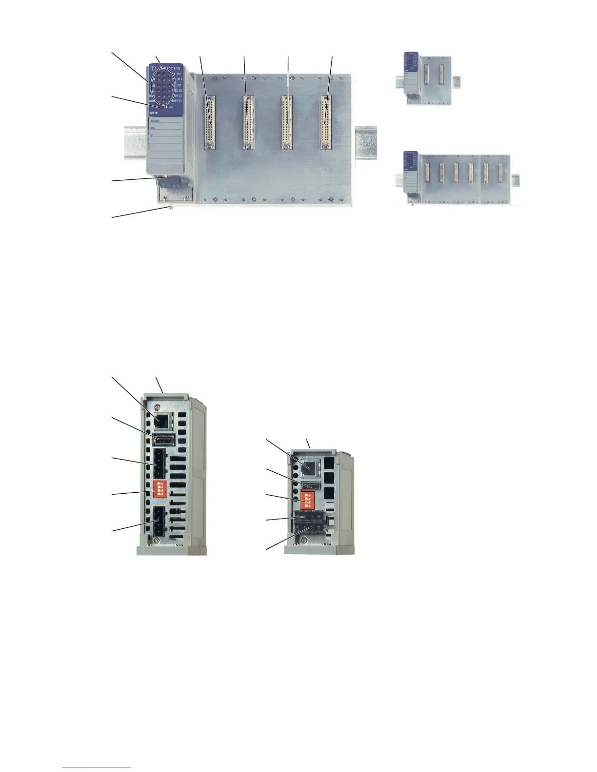
Figure 2: Overview interfaces, display elements and controls of the MS20 -...
1 - Grounding screw
2 - Terminal block, V.24 port, USB port, DIP switch
3 - Key for display status
4 - Switch basic module MS20-...
5 - LEDs for device status, display status
6 - 4 slots for media modules MM2-... or MM3-... with 2-4 ports each
Figure 3: Interfaces of the MS20-... and MS30-... on the bottom of the device
1 - Terminal block (power 2)
2 - DIP switch
3 - Terminal block (power 1)
4 - USB port
5 - V.24 port
6 - MICE MS20/30 switch basic module with 18 to 60 VDC voltage range
7 - Terminal block (power 2)

 Loading...