Installation MS20/MS30
Release
11
07/2013
35
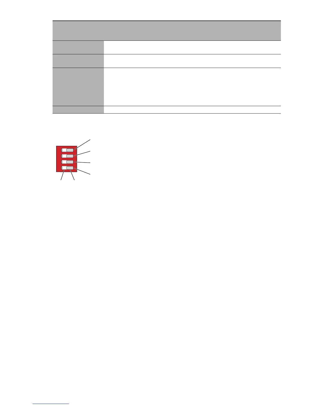
Figure 14: 4-pin DIP switch on the MICE basic module MS20-.../MS30-...
1 - Switch 1, Function: Redundancy Manager (RM)
2 - Switch 2, Function: Ring port
3 - Switch 3, Function: Stand-by
4 - Switch 4, Function: Configuration
5 - Switch position OFF
6 - Switch position ON
Before starting operation of the device, check whether the default settings
of the DIP switch correspond to your requirements.
2.6 Adjusting the DIP switch settings on the
MS20/MS30-...E... basic module (3-pin DIP
switch)
The 3-pin DIP switch on the bottom panel of the basic module gives you the
following options:
RM
switch
position
Stand-by
switch
position
Ring
redund
ancy
Coup-
ling
switch
Ring
manager
Coupling
manager
Ring
port
Control
port
Coup-
ling port
OFF OFF on on off off see
above
ON OFF on on on off see
above
OFF ON on on off on see
above
Module 1/
port 3
(MS20)
module 2/
port 3
(MS30)
Module 1/
port 4
(MS20)
module 2/
port 4
(MS30)
ON ON off off off off
Table 7: Switching redundancy mode and stand-by on/off

 Loading...