34
Installation MS20/MS30
Release
11
07/2013
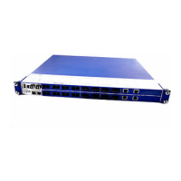
Figure 13: Installing an SFP transceiver
2.5 Adjusting the DIP switch settings on the
basic module (4-pin DIP switch)
The 4-pin DIP switch on the bottom panel of the basic module gives you the
following options:
DIP switch Function State on delivery
RM (redundancy
manager)
a
a. You can use the "RM" and "Stand-by" switches on the 4-pin DIP switch to switch the
following functions on and off (see table 7)
When the HIPER-Ring function is
switched on, you can switch the RM
(Redundancy Manager) function on and
off (see "User Manual - Redundancy
Configuration").
OFF position (RM function
deactivated)
Ring port
b
b. The "Ringport" switch on the 4-pin DIP switch enables you to select the ring ports for the
HIPER-Ring (see table 6)
Selecting the ports for the HIPER-Ring
MS30: In the ON position, ports 1 and 2 in
module 2 form the connection for the
HIPER-Ring.
MS20: In the ON position, port 1 from
modules 1 and 2 form the connection for
the HIPER-Ring.
OFF position (ports 1 and 2 in
module 1 form the connection
for the HIPER-Ring).
Stand-by
a
With the redundant coupling of rings, you
assign the redundancy function to the
MICE in the redundant line (see "User
Manual - Redundancy Configuration").
OFF position (normal function)
SW Configuration /
DIP Configuration
OFF: Give the software configuration
precedence over of the DIP switch
position. In this case, the other switch
positions are meaningless.
OFF position (SW configuration
has precedence)
Switch "Ring port"
position
MICE device Ring ports for the HIPER-Ring
OFF MS20 Module 1/ port 1 and module 1/ port 2
ON MS20 Module 1/ port 1 and module 2 / port 1
OFF MS30 Module 1/ port 1 and module 1 / port 2
ON MS30 Module 2 / port 1 and module 2 / port 2
Table 6: Selecting ring ports for the HIPER-Ring

 Loading...