46
Installation MS20/MS30
Release
11
07/2013
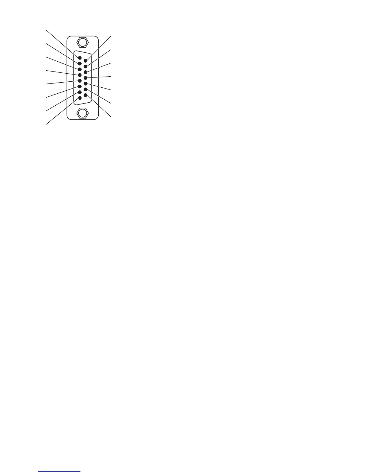
Figure 19: Pin assignment of an AUI interface
1 - Pin 1: Shielding CI
2 - Pin 2: Output CI-A
3 - Pin 3: Input DO-A
4 - Pin 4: Shielding DI
5 - Pin 5: Output DI-A
6 - Pin 6: GND
7 - Pin 7: Not contacted
8 - Pin 8: Shielding CO
9 - Pin 9: Output CI-B
10 - Pin 10: Input DO-B
11 - Pin 11: Shielding DO
12 - Pin 12: Output DI-B
13 - Pin 13: Voltage 12 V
14 - Pin 14: Shielding 12 V
15 - Pin 15: Not contacted
Connect the ports of the media modules plugged into the basic module as
required in order to set up your industrial Ethernet or expand your existing
network.
Install the data lines according to your requirements.

 Loading...