9
English
WARNING:
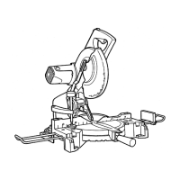
Please be aware of the reaction of the Motor Head (Fig. 1) when
the brake is activated. Braking causes the Motor Head to jerk
downward and the user should be prepared for this reaction,
especially when the trigger switch is released before the blade is
completely down. Failure to be familiar with, and prepared for, the
operational characteristics of the tool may cause serious injury.
AFTER CONNECTING THE POWER PLUG TO AN
APPROPRIATE AC POWER SOURCE, CHECK THE
OPERATION OF THE TOOL AS FOLLOWS:
11. Trial Run
After confi rming that no one is standing behind, the power tool start and
confi rm that no operating abnormalities exist before attempting a cutting
operation.
12. Inspect the rotating stability of the saw blade.
For precise cutting, rotate the saw blade and check for defl ection to
confi rm that the blade is not noticeably unstable; otherwise vibrations
might occur and cause an accident.
BEFORE CUTTING
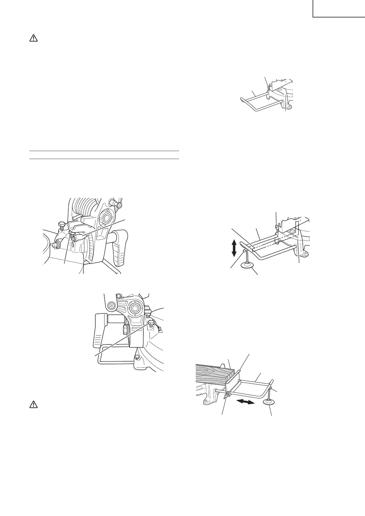
1. Oblique angle
Before the power tool is shipped from the factory, it is adjusted for 0°, left
45° bevel cutting angle with the 8mm bolt (A) and the 8mm bolt (B).
When changing the adjustment, change the height of the 8mm bolt (A)
or the 8mm bolt (B) by turning them. (Fig. 8-a, Fig. 8-b)
8mm Bolt (A)
(Stopper for 0°)
Indicator (B)
(For bevel scale)
Fig. 8-a
8mm Bolt (B) (Stopper
for left 45° bevel angle)
Fig. 8-b
2. Securing the workpiece
WARNING:
Always clamp or vise to secure the workpiece to the fence;
otherwise the workpiece might be thrust from the table and cause
bodily harm.
3. Installing the holder ... (Optional accessory)
The holder helps keep longer workpieces stable and in place during the
cutting operation.
○
As indicating in Fig. 9, installing the holder in the holes on the side of base
and fasten it with 6 mm machine screw (Optional accessory).
Base
6 mm Machine screw (Optional accessory)
Holder (Optional accessory)
Fig. 9
4. Installing the holders ... (Optional accessory)
The holders help keep longer workpieces stable and in place during the
cutting operation.
(1) As indicated in Fig. 10, use a steel square for aligning the upper edge of
the holders with the base surface.
Loosen the 6mm wing nut. Turn a height adjustment bolt 6mm, and adjust
the height of the holder.
(2) After adjustment, fi rmly tighten the wing nut and fasten the holder with the
6mm wing bolt (optional accessory). If the length of Height Adjustment
Bolt 6mm is insuffi cient, spread a thin plate beneath. Make sure the end
of Height Adjustment Bolt 6mm does not protrude from the holder.
6mm Wing bolt
(Optional accessory)
Holder
(Optional
accessory)
Base surface
6mm Wing nut
(Optional accessory)
Height adjustment bolt 6mm
(Optional accessory)
Steel square
Fig.10
5. Stopper for precision cutting ... (Stopper and holder are optional
accessory)
The stopper facilitates continuous precision cutting in lengths of 11 in. to
17-3/4 in. (280mm to 450mm).
To install the stopper, attach it to the holder with the 6mm wing bolt as
shown in Fig. 11.
Workpiece
Stopper
(Optional accessory)
6mm Wing bolt
(Optional accessory)
Holder
(Optional accessory)
Move
6mm Wing nut
(Optional accessory)
Height adjustment bolt 6mm
(Optional accessory)
Fig. 11
0000BookC10FCG.indb90000BookC10FCG.indb9 2017/03/0814:01:072017/03/0814:01:07

 Loading...