89 | 106
Section 6 - WEB Interface
1. Overview
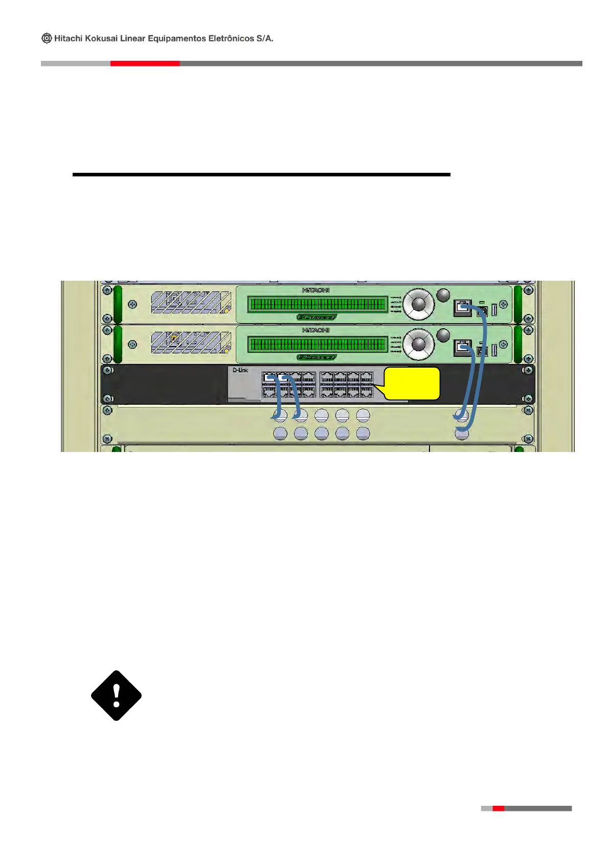
The system configuration can also be performed by the Ethernet connection on Switch Module of this
equipment. This interface enables the interaction between the system control and the user. In order to
access the interface, a PC should be connected to the Ethernet port, using a UTP CAT5 with RJ45
connectors with standard EIA / TIA- 568- B, both connected to the Switch.
All of the equipment parameters such as: transmission power level, power supply measurements, alarm
verification and all the possible functional selections may be accessed two different ways.
⇨ Frontal Panel – Through the frontal panel all of the equipment measurements and configurations
may be accessed, as shown in the operation section.
⇨ Local or remote PC.
It is possible to change and/or monitor all of the parameters and measurements as is done at the frontal
panel through the WEB server. To accomplish this it is necessary to configure the IP / Mask / Gateway.
If the multicast stream is on the same network that will be used for
WEB interface access, a Managed PoE Ethernet Switch must be used
to isolate this access from the multicast stream. For more
information contact Hitachi Technical Assistance.
 Loading...