Chapter 3 General Specifications
3 – 39
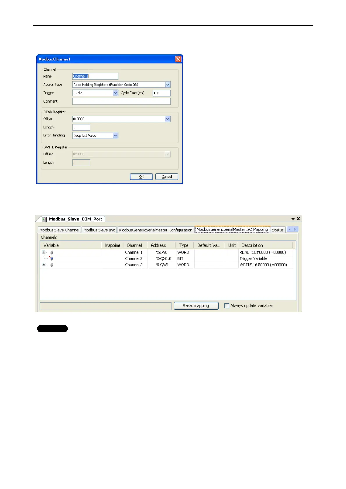
Configure each parameter as below. If the Trigger setting is “Rising edge”, trigger variable (BOOL) will be
automatically assigned in %QX address.
Data of Modbus will be assigned to %IW or %QW as seen in “ModbusGenericSerialMaster I/O Mapping” tab. Read
data from slave is assigned to input area (%IW) and data to be written to slave is assigned to output area (%QW)
Note
When trigger type is set as “Rising edge”, do not change the trigger bit too often, otherwise rising edge could be
missed. Recommended timing is roughly calculated as follows.
T1 is the time from beginning of request to end of response per channel. If several channels are used, the sum of T1,
T2, ..., Tn is the minimum time to keep low or high the trigger bit. But this is very approximate value and it is not easy
to know T1. Recommended time would be 50 to 200ms or more depending on the number of channels.

 Loading...


