Chapter 2 Specifications
2 – 69
2.9 Special modules
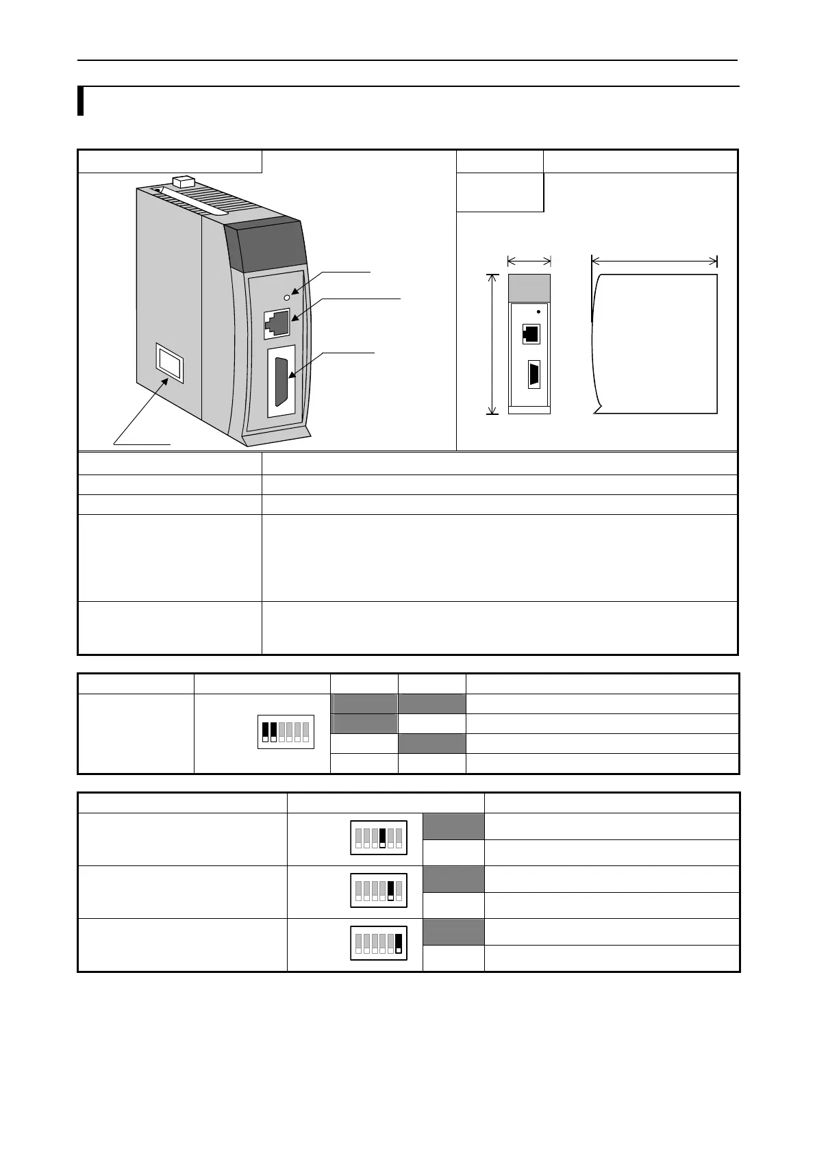
2.9.1 Positioning module : EH-POS
Module features Type (Weight) EH-POS (Approx. 0.17kg (0.37lb.))
Dimensions
(mm (in.))
Reset switch
Positioner connector
I/O connector
DIP switch
30 (1.18)
100 (3.94)
95 (3.74)
Name Description
Reset switch Hardware-reset switch.
Positioner connector This is used for connecting a special programming console called positioner.
I/O connector This is a connector (20 pins) for the pulse output and the external control input.
Applicable connector
Manufacturer: Sumitomo 3M
Connecting system: 10120-3000VE (Soldering type )
Shell: 10320-52F0-008 (or equivalents)
DIP switch Switches the choice of pulse output method (CW/CCW or CK/Direction switching), output logic
(positive/negative logic), and whether external input signal is in or not.
Turn off the power and remove the module out of the base to change the setting.
Purpose Applied switch Bit 1 Bit 2 Explanation
Choice of OFF OFF Clock pulse / Direction signal output (Positive logic)
pulse output method OFF ON Clock pulse / Direction signal output (Negative logic)
ON OFF CW/CCW pulse output (Positive logic)
Bit 1-2
ON
1 2 3 4 5 6
ON ON CW/CCW pulse output (Negative logic)
Purpose Applied switch Explanation
OFF COIN signal
Positioning complete external input
signal
Choice of (COIN) is in or not
Bit 4
ON
1234 56
ON No COIN signal
OFF +0.RUN signal
+ Direction overrun external input signal
Choice of (+0.RUN) is in or not
Bit 5
ON
12345 6
ON No +0.RUN
OFF -0.RUN signal
- Direction overrun external input signal
Choice of (-0.RUN) is in or not
Bit 6
ON
123456
ON No -0.RUN signal
Always use Bit 3 with OFF.

 Loading...


