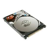
Figure 1-17 DB60
Item Description Item Description
1 Power Supply 2 RDY (Ready) LED, Green. ON when power
supply is operating normally
3 AC IN LED, Green. ON when AC is
supplied to the power supply.
4 ALM (Alarm) LED. RED. ON when power
supply has failed. OK to remove unit.
5 AC receptacle 6 POWER LED Green. ON when power is
applied to the ENC Unit
7 LOCATE LED Amber. ON to assist locating
the ENC Unit during maintenance
operations
8 ALARM LED. RED. ON when the ENC Unit has
failed. OK to remove unit.
9 RG45 ethernet connector (LAN) 10 ENC path IN cable connector
11 ENC path OUT cable connector 12 ENC Unit. Interface between the drives and
the ENC data/control cable
Cache memory
The HUS VM can be configured with up to 256 GB of cache memory. Each
HUS VM system contains two Main blades as shown in the following
illustration. Each Main blade contains a single main board with 32, 64, 96, or
128 GB of cache memory. Main blades are installed in pairs and work
together to provide cache and shared memory for the system.
1-16
Introduction
Hitachi Unified Storage VM Block Module Hardware User Guide
 Loading...

