What causes input phase failure detection in Hitachi L300P Inverter?
- NnewingSep 8, 2025
If the Hitachi Inverter detects an input phase failure, it may be due to a missing phase or contact failure in MCB, Mg.
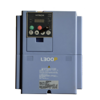
What causes input phase failure detection in Hitachi L300P Inverter?
If the Hitachi Inverter detects an input phase failure, it may be due to a missing phase or contact failure in MCB, Mg.
What causes IGBT over current detection in Hitachi L300P?
If the Hitachi Inverter detects an IGBT over current (equivalent as power module), it could be due to a short circuit or earth contact (ground fault) in the motor or motor cable, an IGBT failure, or a loose connection on the main circuit such as the power board.
Why Hitachi L300P is waiting for AC incoming voltage recovery?
If the Hitachi Inverter experiences a power off or is waiting for AC incoming voltage recovery, it could be due to a drop in the incoming AC voltage. Check the DC bus voltage. Also, check for contact failure in MCB, Mg.
What to do if Hitachi L300P Inverter displays encoder wire cut error?
If the Hitachi Inverter shows an encoder wire cut, check the wiring for breaks or loose connections of the encoder signal. Replace the encoder if it has failed or is not a line driver output. If using an encoder without a Z phase signal, set SWENC-2 to “OFF” on the card.
What to do if Hitachi L300P Inverter displays connection error?
If a Hitachi Inverter shows a connection error, make sure the connection of the board and if the usage is proper.
What to do if Hitachi Inverter displays option card error?
If a Hitachi Inverter displays an option card error, make sure the connection of the board and if the usage is proper.
Details precautions for working with high voltage components and protecting against electric shock.
Provides a step-by-step guide for installing the inverter, covering mounting, wiring, and testing.
Guides the user on preparing for wiring, including cutting grommets and reviewing warnings.
Provides tables and notes for determining appropriate wire and fuse sizes for inverter applications.
Provides a procedure and checklist for performing the initial powerup test of the inverter.
Guides on selecting functions and editing parameters for motor operation, including base frequency settings.
Provides a checklist and steps to run the motor for the first time after parameter setup.
Lists and describes functions for monitoring inverter parameters like output frequency, current, and voltage.
Covers main profile parameters including output frequency, acceleration, and deceleration time settings.
Explains how to adjust analog input characteristics for controlling inverter output frequency.
Details parameters for configuring DC braking for deceleration and starting, including force and time settings.
Explains the built-in PID loop for controlling external processes and associated parameters.
Covers parameters for fine-tuning motor control and system configuration, including restart modes.
Describes the inverter's function to automatically adjust output frequency to limit overload.
Explains the software lock function to prevent accidental parameter changes and how to exclude output frequency.
Details the configuration of intelligent input and output terminals for inverter control and monitoring.
Lists parameters for configuring inverter motor characteristics, including capacity and pole settings.
Details the built-in PID loop for controlling external processes and associated parameters.
Provides safety messages and general precautions before performing troubleshooting or maintenance.
Explains how to access and interpret trip events, history, and conditions using the inverter's monitor functions.
Provides instructions for restoring all inverter parameters to their original factory default settings.



 Loading...