10 Servicing
337
10
SMGB0077 rev.0 - 01/2013
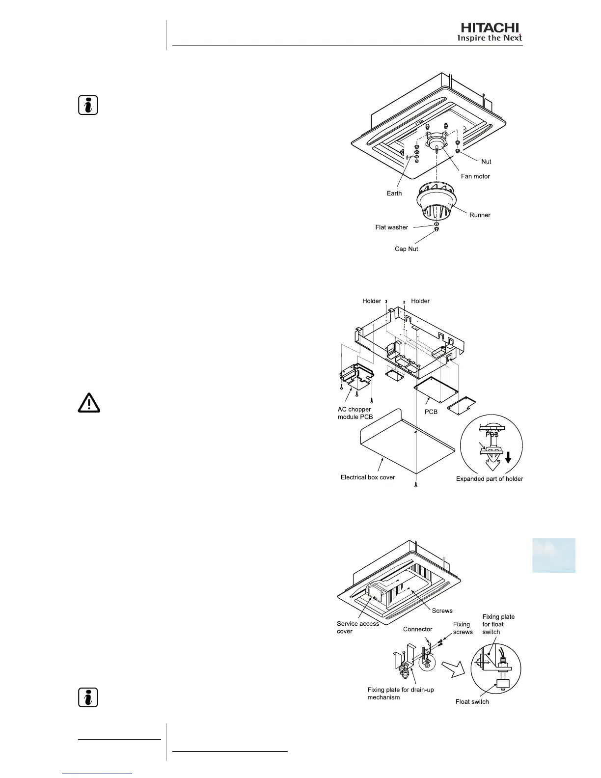
Remove the cap nut and the washer securing the fan duct and
remove it.
N O T E
• Torque value: maximum 8 Nm.
• RCD-(1.5-3.0)FSN2: one duct and one fan motor.
• RCD-(4.0-5.0)FSN2: two ducts and two fan motors.
Separate the connector from the fan motor earth cable.
Remove the four nuts securing the fan motor and remove it.
10.4.5 Removal of the printed circuit board (PCB)
Remove the air inlet grille as indicated in chapter Removal of the
optional air panel.
Remove the electrical box as indicated in chapter Removal of the
electrical box.
Remove the printed circuit board (PCB) by pressing carefully on
the support tabs with long-tipped pliers, as shown in the gure.
Remove the three set screws from the AC chopper.
C A U T I O N
• Do not touch the electrical components of the PCB.
• Do not apply force to the PCB, as this could damage it.
• The sealed earthing cable and the transformer are secured
by a screw. When installing, be particularly careful not to
overtighten the set screw.
10.4.6 Removal of the oat switch
Remove the air inlet grille as indicated in chapter Removal of the
long-lasting lter and the air inlet grille.
Remove the bellmouth in line with the instructions given in chapter
Removal of the fan duct and the fan.
Remove the two screws securing the panel located next to the
service opening, close to the pipes inside the unit and remove it.
Separate the oat switch connector and remove the two screws
securing the plate attaching the switch to the drain mechanism
securing plate.
Loosen the resin nut securing the oat switch and remove it.
N O T E
The torque value of the resin nut is 0.3 - 0.4 Nm. If the torque
value is higher, the nut will be damaged.
 Loading...


