10 Servicing
366
SMGB0077 rev.0 - 01/2013
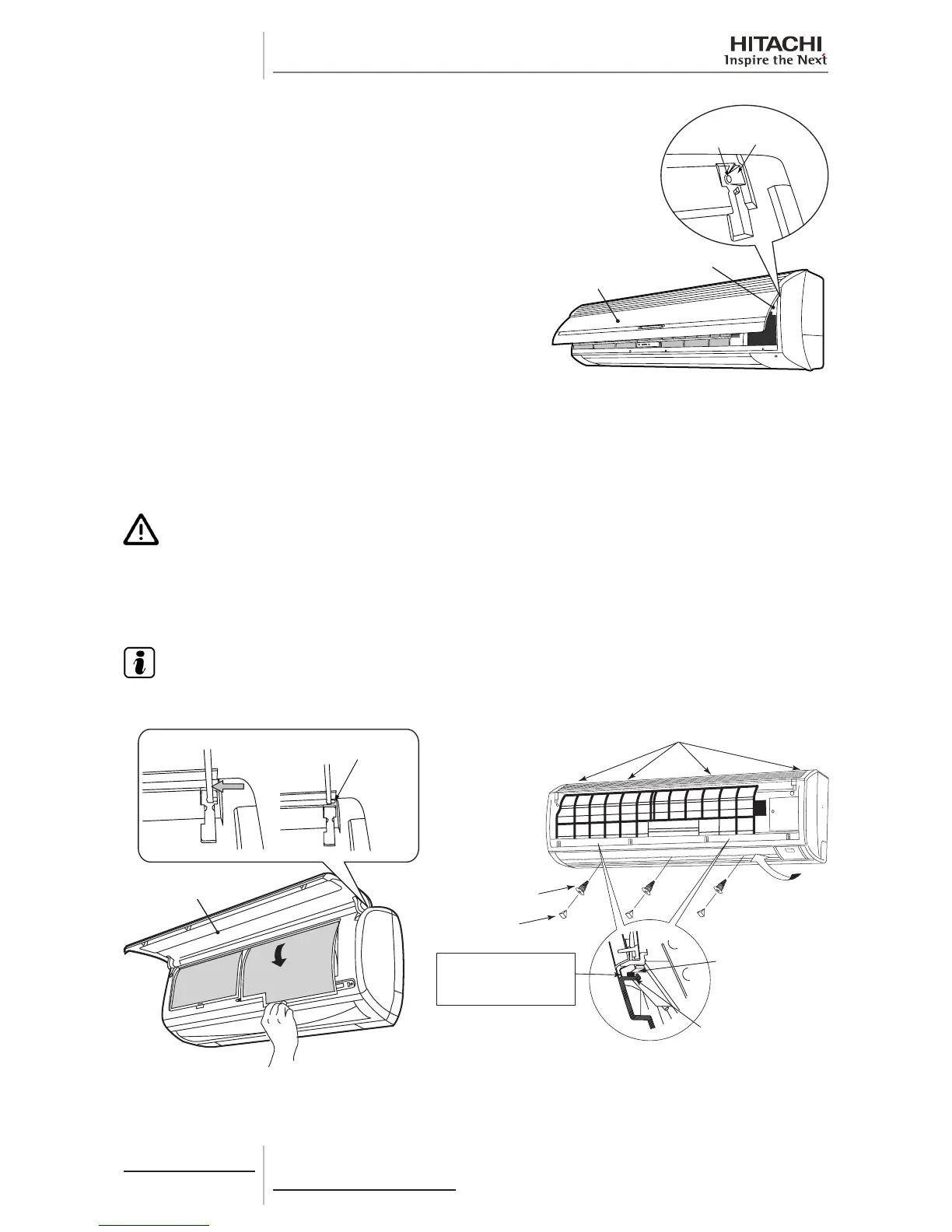
Attaching at panel.
Insert completely the left and right arm shafts of at panel into
the holes along the guide at the front panel. Ater the at panel is
attached completely, insert the catches for air lter to x it.
Hole
Guide at
Front Panel
Front Panel
Flat Panel
For RPK-(2.0-4.0)FSN(H)3M
1 Remove the air lter according to the “Removing Air Filter.” chapter.
2 Open the at panel fully and push the right arm shaft inward. After the shaft is removed from the front panel, pull the
at panel frontward with the right arm shaft slightly pushed inward and then remove the at panel.
3 Remove 3 bushes and then 3 screws. Pull the lower side of the front panel (2 portions) forward to release the catches.
Use a slotted screwdriver when the catches are difcult to release.
C A U T I O N
Takespecialcarenottobeinjuredbytheheatexchangerns.
4 Remove the front panel carefully so that it does not touch the horizontal louver attached to the air outlet. Slightly lift
the front panel up to release the catches (4 portions) on the upper side of the unit. Then pull the front panel forward
to remove it.
N O T E
When releasing the catches, snap sound is heard. This is the sound made when the catches are released
and so there are no safety concerns.
Flat panel
Push the shaft
toward arrow
direction
Remove this part
from the hole
Screw
Bush
Catches on Lower Side
of Front Panel
When using a slotted
screwdriver, insert it
into the gap and push
the catches downwarads.
Drain Pan Projection
Portion for Catches
5 When mounting the front panel, be careful that it does not touch the horizontal louver. Paying attention to both sides of
the panel, put the catches (four portions) on the upper side of the unit into the holes on the panel. Then push the lower
side of the panel (2 portions) to fasten the catches.
 Loading...


