Appendix
79
Assembly instructions
Linear Guideways
GW-04-0-EN-1910-MA
Dimensions of rail HGR_R
Series/
size
Assembly screw
for rail [mm]
Dimensions of rail [mm] Max. length
[mm]
Max. length
E
1
= E
2
[mm]
Min. length
[mm]
E
1/2
min
[mm]
E
1/2
max
[mm]
Weight
[kg/m]
W
R
H
R
DhdP
HGR15R M4 × 20 15 15.0 7.5 5.3 4.5 60 4,000 3,900 132 654 1.45
HGR20R M5 × 20 20 17.5 9.5 8.5 6.0 60 4,000/5,600
1)
3,900/5,520
1)
134 753 2.21
HGR25R M6 × 25 23 22.0 11.0 9.0 7.0 60 4,000/5,600
1)
3,900/5,520
1)
136 852 3.21
HGR30R M8 × 3, 28 26.0 14.0 12.0 9.0 80 4,000/5,600
1)
3,920/5,520
1)
178 971 4.47
HGR35R M8 × 35 34 29.0 14.0 12.0 9.0 80 4,000/5,600
1)
3,920/5,520
1)
178 971 6.30
HGR45R M12 × 45 45 38.0 20.0 17.0 14.0 105 4,000/5,600
1)
3,885/5,460
1)
234 12 93 10.41
HGR55R M14 × 55 53 44.0 23.0 20.0 16.0 120 4,000/5,600
1)
3,840/5,440
1)
268 14 106 15.08
HGR65R M16 × 65 63 53.0 26.0 22.0 18.0 150 4,000/5,600
1)
3,750/5,350
1)
330 15 135 21.18
1)
Optional version on request
L
h
P
E
1
E
2
W
R
H
R
Ød
Dimensions of rail HGR_T
Series/
size
Dimensions of rail [mm] Max. length
[mm]
Max. length
E
1
= E
2
[mm]
Min. length
[mm]
E
1/2
min
[mm]
E
1/2
max
[mm]
Weight
[kg/m]
W
R
H
R
ShP
HGR15T 15 15.0 M5 860 4,000 3,900 132 654 1.48
HGR20T 20 17.5 M6 10 60 4,000 3,900 134 753 2.29
HGR25T 23 22.0 M6 12 60 4,000 3,900 136 852 3.35
HGR30T 28 26.0 M8 15 80 4,000 3,920 178 971 4.67
HGR35T 34 29.0 M8 17 80 4,000 3,920 178 971 6.51
HGR45T 45 38.0 M12 24 105 4,000 3,885 234 12 93 10.87
HGR55T 53 44.0 M14 24 120 4,000 3,840 268 14 106 15.67
HGR65T 63 53.0 M20
1)
30 150 4,000 3,750 330 15 135 21.73
1)
R
h
E
1
E
2
P
L
S
W
R
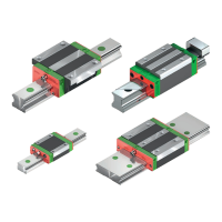
12.5 Technical data for rails
12.5.1 Dimensions of the HG rails
The HG rails are used for both the HG and QH blocks.
HGR_R
HGR_T
Note:
1. The tolerance for E is +0.5 to –1 mm for standard rails and 0 to –0.3 mm for joint connections.
2. If the E
1/2
dimensions are not indicated, the maximum possible amount of fixing holes will be determined with regard to the E
1/2
min.
3. The rails are shortened to the required length. If the E
1/2
dimensions are not indicated, these will be carried out symmetrically.
 Loading...