EasyManuals Logo

Hobart Handler 140 User Manual

Hobart Handler 140
48 pages
To Next Page IconTo Next Page
To Previous Page IconTo Previous Page
Page #17 background imageLoading...
Page #17 background image
. A complete Parts List is available at www.HobartWelders.com
OM-925 Page 13
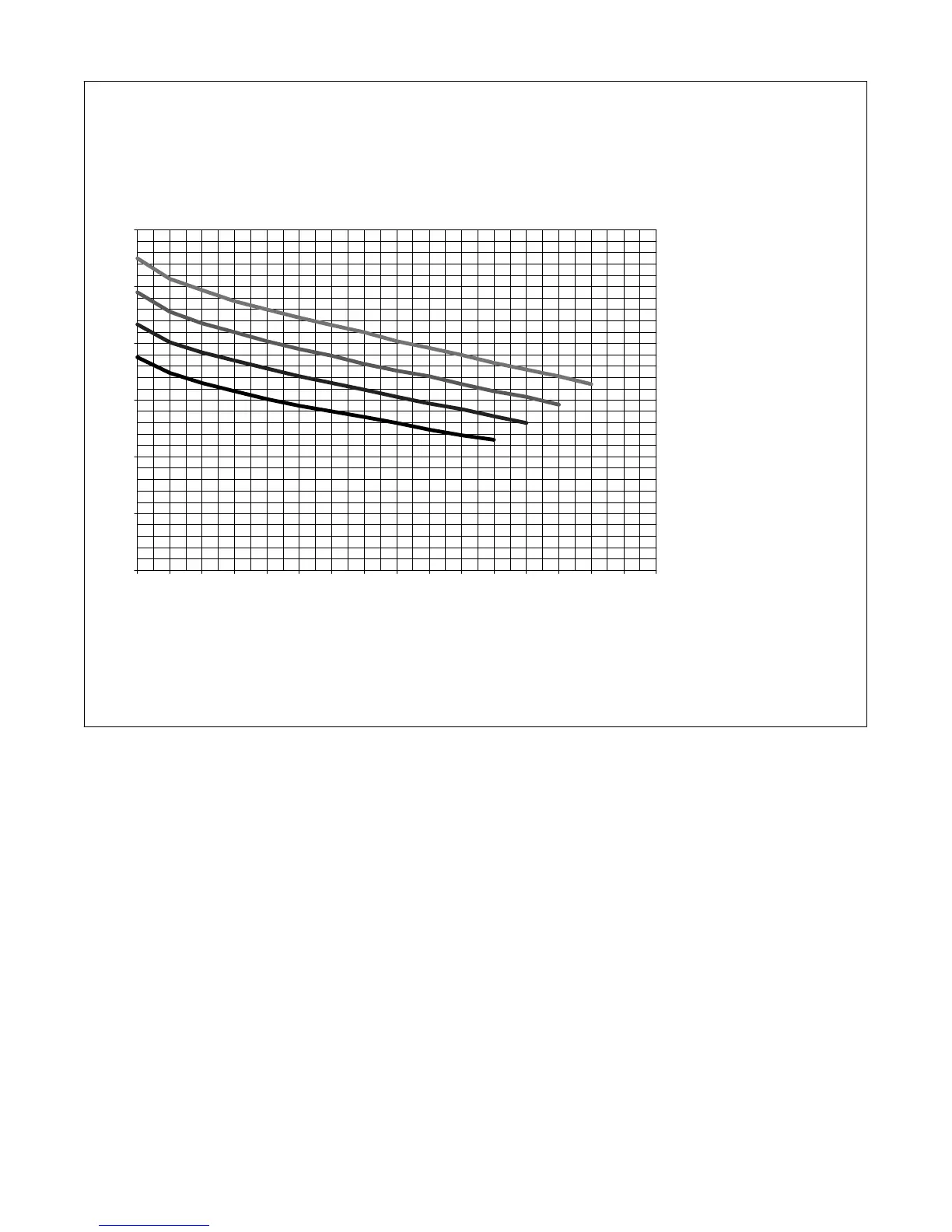
4-3. Volt-Ampere Curves
The volt-ampere curves show the
minimum and maximum voltage
and amperage output capabilities of
the welding power source. Curves
of other settings fall between the
curves shown.
ssb1.1 10/91 217 624-A
RANGE 4
RANGE 3
RANGE 2
RANGE 1
0 10 20 30 40 50 60 70 80 90 100 110 120 130 140 150 160
0.0
5.0
10.0
15.0
20.0
25.0
30.0
Amperage
Voltage

Table of Contents

Other manuals for Hobart Handler 140

Questions and Answers:

Question and Answer IconNeed help?

Do you have a question about the Hobart Handler 140 and is the answer not in the manual?

Hobart Handler 140 Specifications

General IconGeneral
Input Voltage115V
Welding Amperage Range25-140 A
Duty Cycle20% @ 90A
Wire Feed Speed Range40-700 IPM
Weldable MaterialsMild Steel, Stainless Steel, Aluminum
Weight57 lbs
ProcessesMIG (GMAW), Flux-Cored (FCAW)
Input Current20A
Welding Thickness24 ga. - 1/4 in.
Input PhaseSingle Phase
Maximum Open Circuit Voltage28V
Wire Size Range0.023 - 0.035 in

Related product manuals