. A complete Parts List is available at www.HobartWelders.com
OM-925 Page 22
SECTION 6 − OPERATION
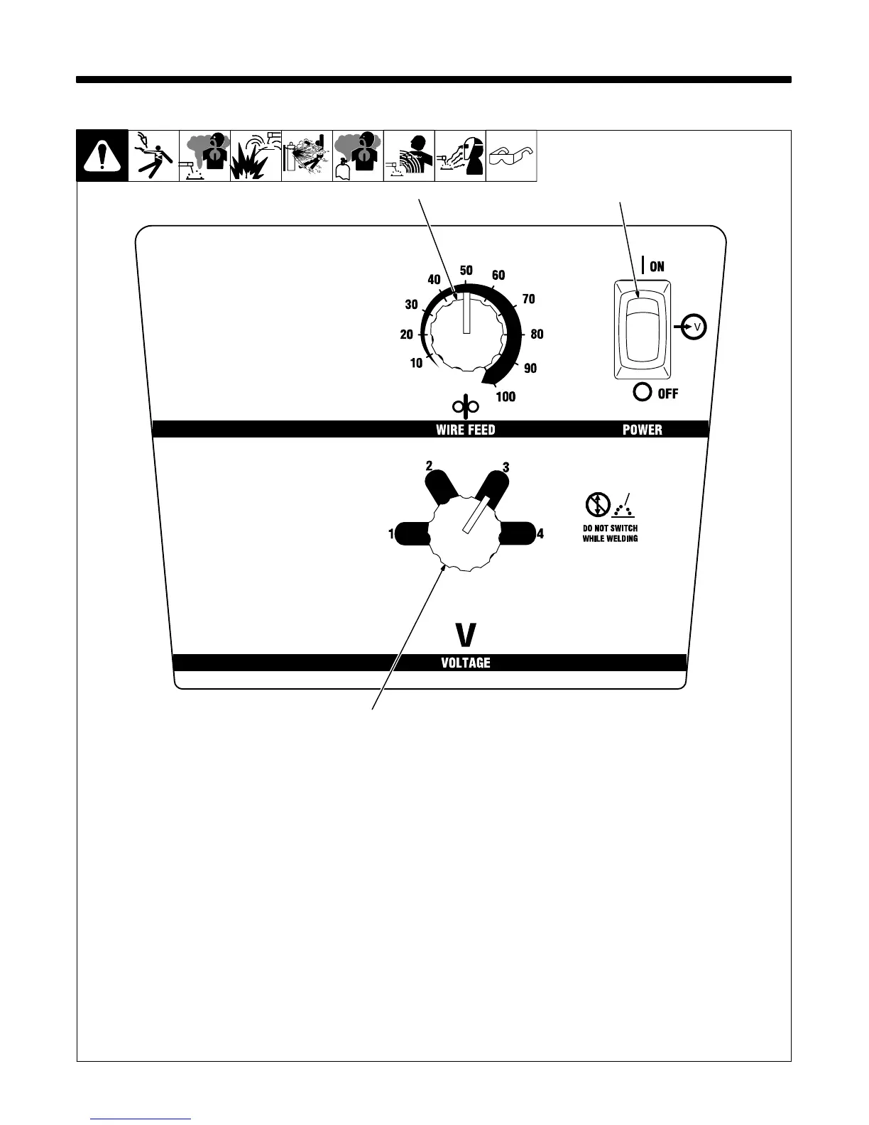
6-1. Controls
1 Wire Speed Control
Use control to select a wire feed speed. As
Voltage switch setting increases, wire
speed range also increases (see weld
setting label in welding power source or
Section 6-2).
2 Power Switch
3 Voltage Switch
The higher the selected number, the
thicker the material that can be welded
(see weld setting label in welding power
source or Section 6-2). Do not switch under
load.
. Switch must “click” into detent
position for weld output.
Ref. 230 002-A
2
3
1
NE PAS CHANGER
DE PROCÉDÉ