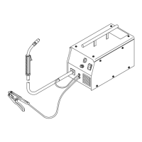
. A complete Parts List is available at www.HobartWelders.com
OM-925 Page 17
5-6. Serial Number And Rating Label Location
The serial number and rating information for this product is located on back. Use rating label to determine input power requirements and/or rated output.
For future reference, write serial number in space provided on back cover of this manual.
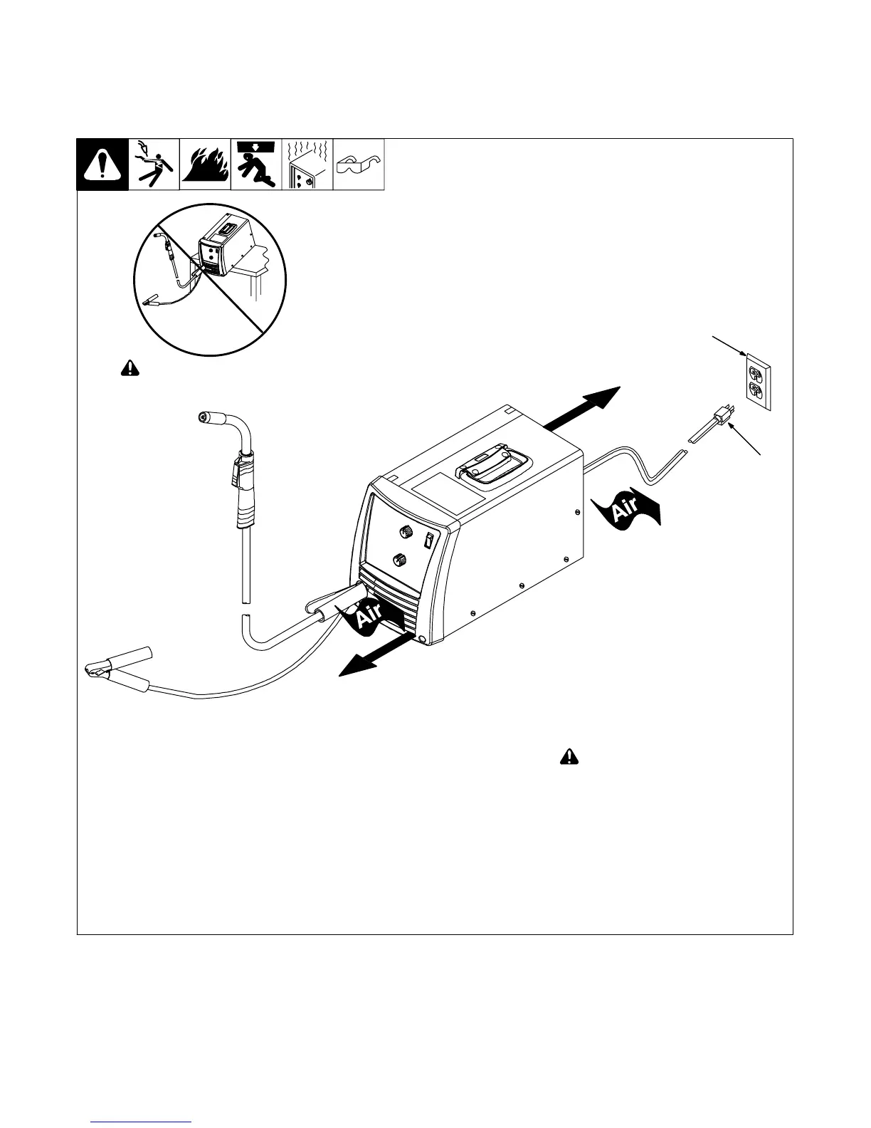
5-7. Selecting A Location And Connecting Input Power
1 Grounded Receptacle
A 115 volt, 20 ampere individual branch
circuit protected by time-delay fuses or
circuit breaker is required.
2 Plug From Unit
Select extension cord of 12 AWG for up to
50 ft (15 m) or 10 AWG for 50 up to 100 ft
(30 m).
! Special installation may be
required where gasoline or volatile
liquids are present − see NEC
Article 511 or CEC Section 20.
2
803 712-C
! Do not move or operate unit
where it could tip.
1
18 in.
(460 mm)
18 in.
(460 mm)