EasyManuals Logo

Hobart Handler 140 User Manual

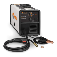
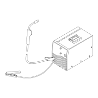
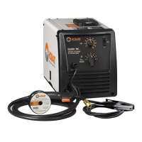
Hobart Handler 140
48 pages
To Next Page IconTo Next Page
To Previous Page IconTo Previous Page
Page #38 background imageLoading...
Page #38 background image
OM-925 Page 34
9-3. Holding And Positioning Welding Gun
. Welding wire is energized when gun trigger is pressed. Before lowering helmet and pressing trigger, be sure wire is no more than 1/2 in. (13 mm)
past end of nozzle, and tip of wire is positioned correctly on seam.
1 Hold Gun and Control Gun
Trigger
2 Workpiece
3 Work Clamp
4 Electrode Extension (Stickout)
1/4 to 1/2 in. (6 To 13 mm)
5 Cradle Gun and Rest Hand on
Workpiece
2
3
5
4
90° 90°
0°-15°
45°
45°
1
0°-15°
S-0421-A
End View of Work Angle Side View of Gun Angle
GROOVE WELDS
End View of Work Angle Side View of Gun Angle
FILLET WELDS
Table of Contents

Other manuals for Hobart Handler 140

Questions and Answers:

Question and Answer IconNeed help?

Do you have a question about the Hobart Handler 140 and is the answer not in the manual?

Hobart Handler 140 Specifications

General IconGeneral
Input Voltage115V
Welding Amperage Range25-140 A
Duty Cycle20% @ 90A
Wire Feed Speed Range40-700 IPM
Weldable MaterialsMild Steel, Stainless Steel, Aluminum
Weight57 lbs
ProcessesMIG (GMAW), Flux-Cored (FCAW)
Input Current20A
Welding Thickness24 ga. - 1/4 in.
Input PhaseSingle Phase
Maximum Open Circuit Voltage28V
Wire Size Range0.023 - 0.035 in

Related product manuals