. A complete Parts List is available at www.HobartWelders.com
OM-925 Page 15
5-3. Process/Polarity Table
Process Polarity
Cable Connections
Cable To Gun Cable To Work
GMAW − Solid wire with shield-
ing gas
DCEP − Reverse polarity Connect to positive (+) out-
put terminal
Connect to negative (−) output
terminal
FCAW − Self-shielding wire −
no shielding gas
DCEN − Straight Polarity Connect to negative (−)
output terminal
Connect to positive (+) output
terminal
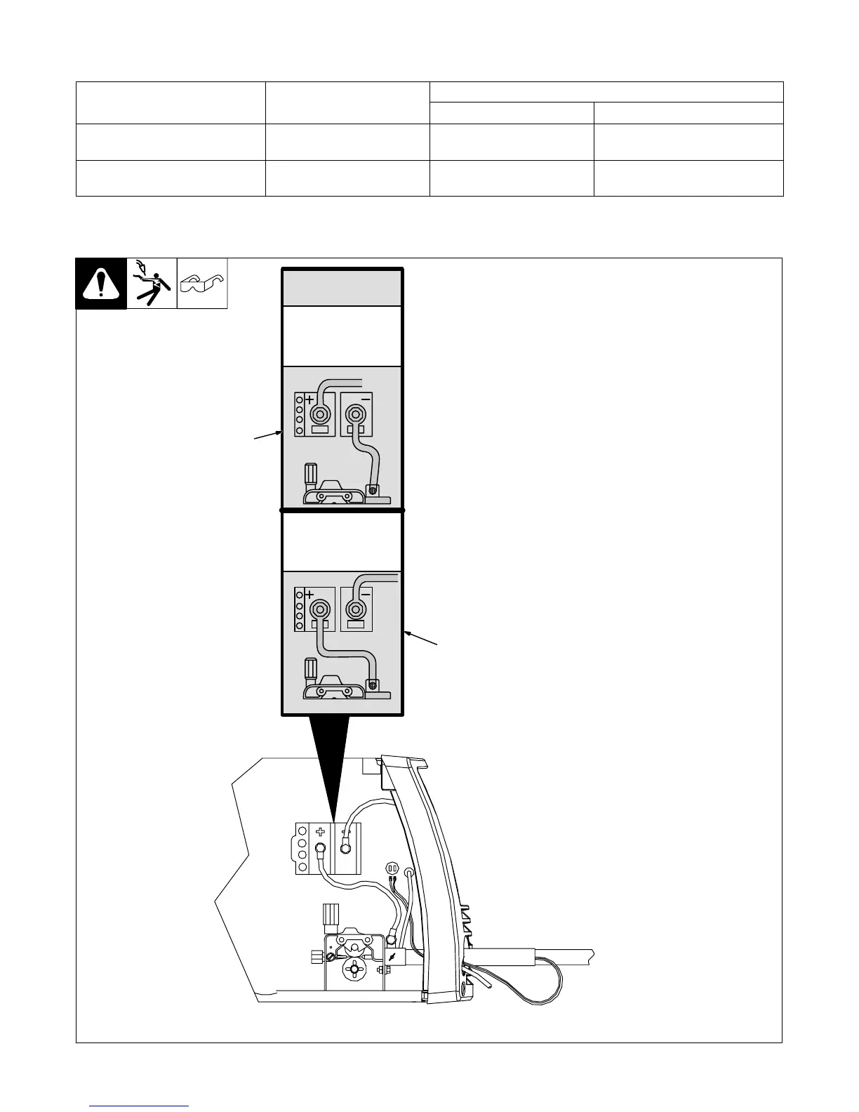
CHANGING
POLARITY
5-4. Changing Polarity
1 Lead Connections For Direct
Current Electrode Negative
(DCEN)
2 Lead Connections For Direct
Current Electrode Positive
(DCEP)
Always read and follow wire
manufacturer’s recommended
polarity, and see Section 5-3.
Close door.
Ref. 209 228 / Ref. 209 229 / Ref. 803 714-A
1
2
DCEN
Electrode negative for
flux cored wire
DCEP
Electrode positive for
solid wire