. A complete Parts List is available at www.HobartWelders.com
OM-925 Page 21
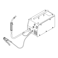
Remove gun nozzle and contact tip.
Ref. 803 714-A
WOOD
Feed wire to check drive roll pressure.
Tighten knob enough to prevent slipping.
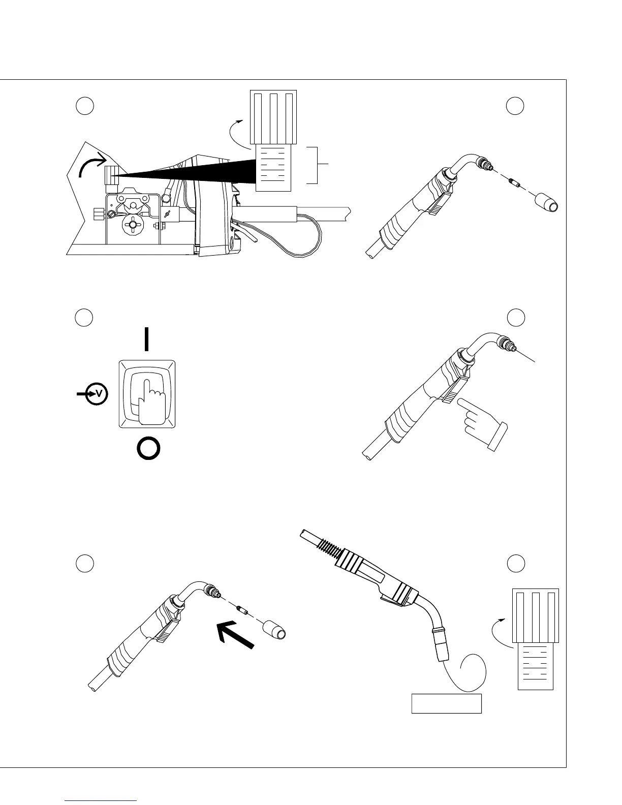
Cut off wire. Close door.
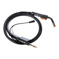
Press gun trigger until wire comes out of gun.
(Keep gun cable as straight as possible.)
Turn power on. Be sure that Voltage range
switch is set to range 1, 2, 3, or 4 to feed wire.
Rotate knob until it “clicks” into detent. Wire
will not feed if range switch is set between
ranges.
Tighten
1
2
3
4
. Use pressure indicator scale to set
a desired drive roll pressure. (Start
with a setting of 2 or 3 on the scale.)
Pressure
Indicator
Scale
Tighten
1
2
3
4
Be sure that wire is positioned in proper feed roll groove.
Close and tighten pressure assembly, and let go of wire.
Be sure that tip matches wire diameter.
Reinstall contact tip and nozzle.
4 5
6 7
8 9