EasyManuals Logo

Hobart Handler 175 User Manual

Hobart Handler 175
48 pages
To Next Page IconTo Next Page
To Previous Page IconTo Previous Page
Page #17 background imageLoading...
Page #17 background image
OM-944 Page 13
3-3. Process/Polarity Table
Cable Connections
Process Polarity
Cable To Gun Cable To Work
GMAW Solid wire with shield-
ing gas
DCEP Reverse polarity Connect to positive (+) out-
put terminal
Connect to negative () output
terminal
FCAW Self-shielding wire
no shielding gas
DCEN Straight Polarity Connect to negative ()
output terminal
Connect to positive (+) output
terminal
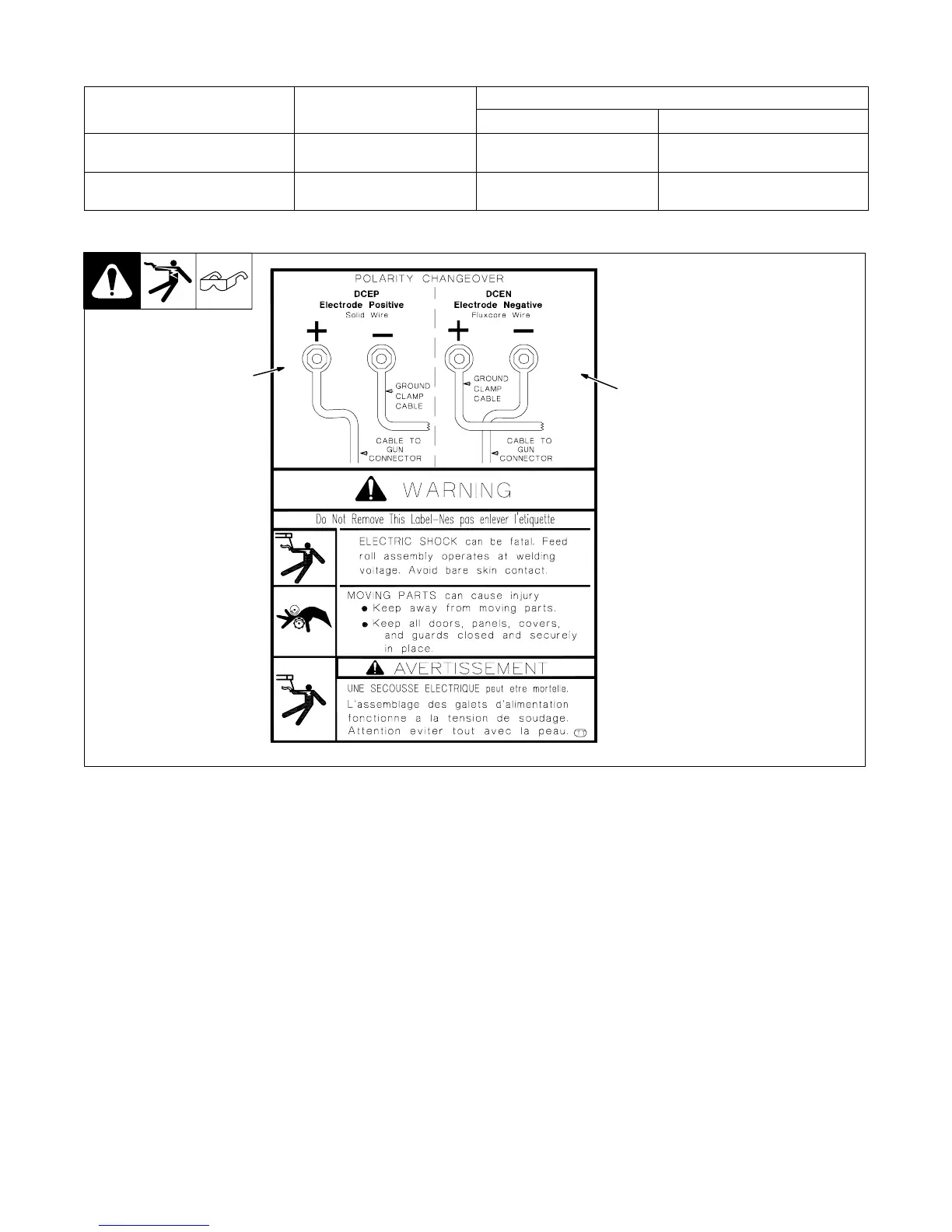
3-4. Changing Polarity
1 Lead Connections For Direct
Current Electrode Positive
(DCEP)
2 Lead Connections For Direct
Current Electrode Negative
(DCEN)
Always read and follow wire
manufacturers recommended po-
larity, and see Section 3-3.
Close door.
1
Ref. 196 052
2

Table of Contents

Questions and Answers:

Question and Answer IconNeed help?

Do you have a question about the Hobart Handler 175 and is the answer not in the manual?

Hobart Handler 175 Specifications

General IconGeneral
Input Voltage230 V
Duty Cycle30% at 130 A
Welding ProcessesMIG (GMAW), Flux-Cored (FCAW)
Input Current20 A
Input PhaseSingle-phase
Input Frequency60 Hz
Welding Amperage Range25 - 175 A
Wire Feed Speed Range40 - 700 IPM
Wire Size Capacity4 or 8 inch spools
Output Current Range30-175A
Wire Size Range0.023-0.045 in

Related product manuals