OM-944 Page 23
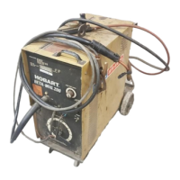
5-4. Changing Drive Roll Or Wire Inlet Guide
1 Inlet Wire Guide Securing
Screw
2 Inlet Wire Guide
Loosen screw. Slide tip as close to
drive rolls as possible without
touching. Tighten screw.
3 Drive Roll
The drive roll consists of two differ-
ent sized grooves. The stamped
markings on the end surface of the
drive roll refers to the groove on the
opposite side of the drive roll. The
groove closest to the motor shaft is
the proper groove to thread (see
Section 3-10). NOTE: when
changing drive rolls, make sure
the woodruff key is on the motor
shaft, and not in the old drive roll.
4 Drive Roll Securing Screw
Secure drive roll with screw as
shown.
Tools Needed:
2
1
3
4
Ref. 802 444 / 802 139
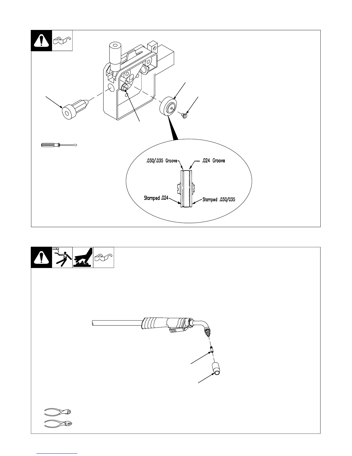
5-5. Replacing Gun Contact Tip
Ref. 802 399-A
Y Turn Off power before
replacing contact tip.
1 Nozzle
2 Contact Tip
Cut off welding wire at contact tip.
Remove nozzle.
Remove contact tip and install new
contact tip. Reinstall nozzle.
Tools Needed:
1
2