Discovery QDR Series Technical Manual
4-28
4.9 Filter Drum Encoder Alignment
1. Attach Ch1 probe to SEGMENT test point (TP3) on the C-Arm Interface board.
2. Attach Ch2 probe to BRASS test point (TP2) on the C-Arm Interface board.
3. Connect probe to ground.
4. Go to X-Ray Survey and turn on the Filter Drum motor.
5. As the filter drum motor turns on and rotates look on the C-Arm Interface board.
a. The yellow “Index” LED blinks (on then off) as the Index mark passes the
optical interrupter.
b. Verify the green “Top of Drum” and “Brass on Top” LED (D8) blink as the
drum spins.
c. The green “AC Lock” LED (D7) lights (steady, not blinking) after a few rev-
olutions of the drum.
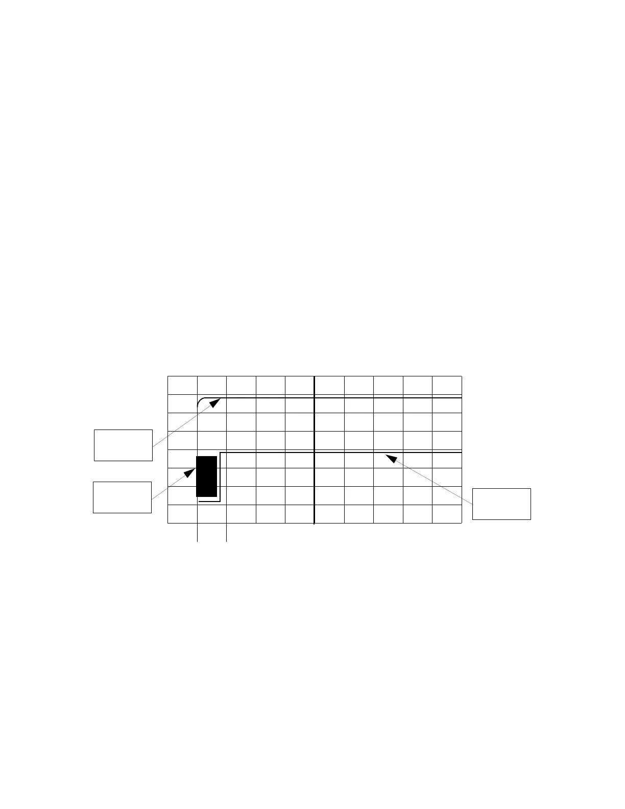
6. Measure from the rising edge of the BRASS to the rising edge of the SEGMENT
(it does not matter which edge leads). The time measured must be less than 500
μs (500 μs = 0.5 ms). See
Figure 4-8 and Figure 4-9.
Figure 4-8 Trigger on CH1
500μs
Segment
Signal
Jigger
Brass
Signal