Discovery QDR Series Technical Manual
2-8
+5VDC. The +5VDC is converted to -5VDC and +/-3VDC. The +/-5VDC powers logic
circuitry on this board, while the +/- 3VDC provides the reference voltage for the position
sensors. Two green LEDs provide visual indication of the +24 and +5VDC status (ON
indicates the respective voltage is present).
The 240VAC power is connected through control relays to the pedestal motors.
2.5.3 Interface Connections
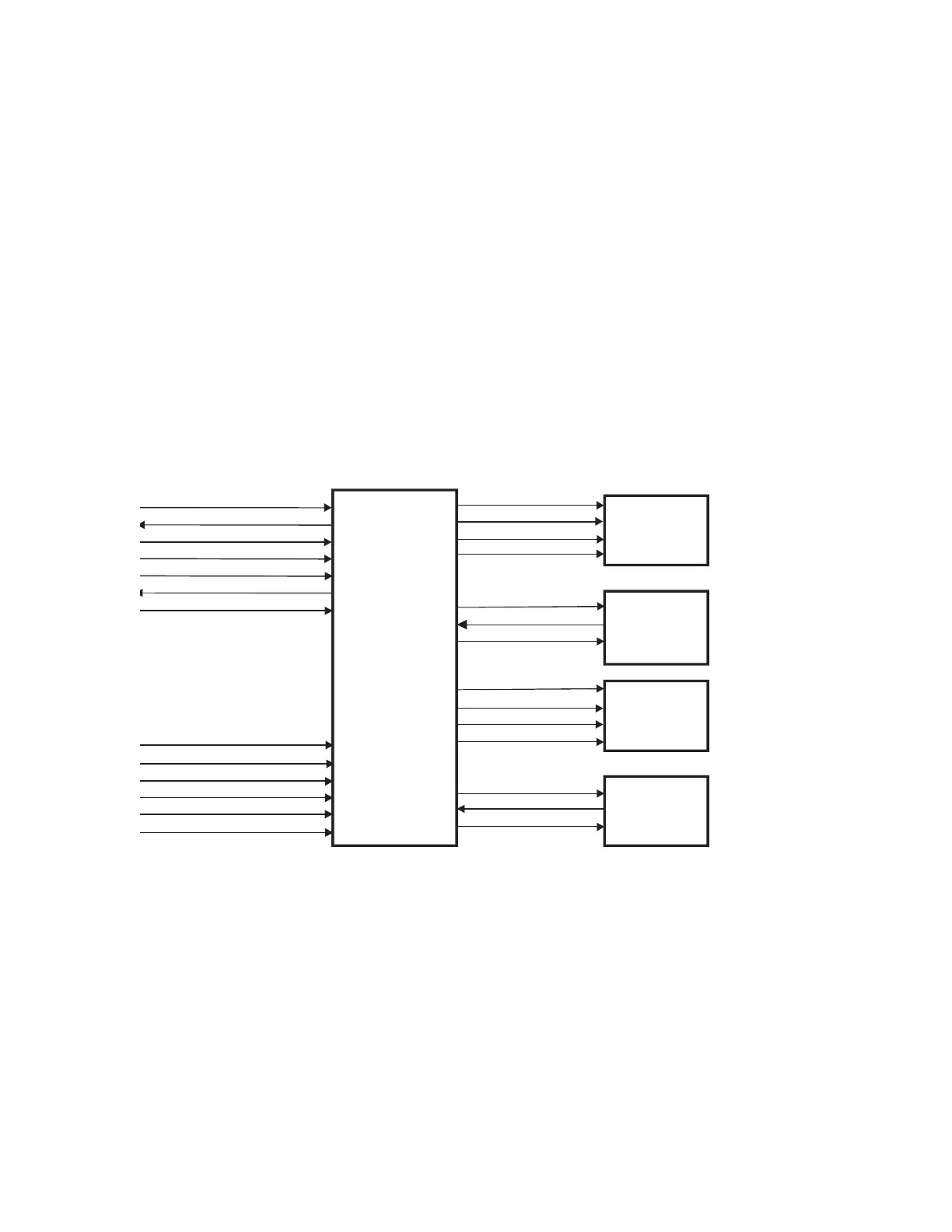
Figure 2-4 shows the interconnections between the Distribution Board, the TZ Drive
Board, the Pedestal Motors, and the Pedestal Position Encoders. Table 2-5 describes the
interconnections between the Distribution Board and the TZ Drive Board. Table 2-6
describes the line voltage (240VAC, line to line) between the DIN Rail Assembly and the
TZ Drive Board. Table 2-7 describes the interconnections between the TZ Drive Board
and the two pedestal motors and their respective position encoders. The tables also
identify the interconnection connector and pin assignments.
Figure 2-4. Distribution Board/TZ Drive Board Interconnection Diagram
Table 2-4 shows the interconnections between the Distribution Board, the TZ Drive
Board, the Pedestal Motors, and the Pedestal Position Encoder, Table 2-5 describes the
interconnections between the Distribution Board and the TZ Drive Board. Table 2-6
describes the line voltage (240VAC line to line) between the DIN Rail Assembly and the
TZ Drive Board. Table 2-7 describes the interconnection between the TZ Drive Board and
the two pedestal motors and their respective position encoders. The tables also identify the
interconnection connectors and pin assignments.
ARD+, ARD-
ATD+, ATD-
SYSRESET+,
EMERGENCY+,
MAN_UP*, MAN_UP_RET
MAN_DOWN*, MAN_DOWN_RET
+24V
120V(A)_UP_LEFT
120V(A)_DWN_LEFT
120V(B)_LEFT
GND_PED
+3.0VREF
(Position Signal)
-3.0VREF
120V(A)_UP_RIGHT
120V(A)_DWN_RIGHT
120V(B)_RIGHT
GND_PED
+3.0VREF
(Position Signal)
-3.0VREF
TZ
ENCODER
120V(A)_RIGHT
120V(B)_RIGHT
GND_PED
120V(A)_LEFT
120V(B)_LEFT
GND_PED