Discovery QDR Series Technical Manual
2-3
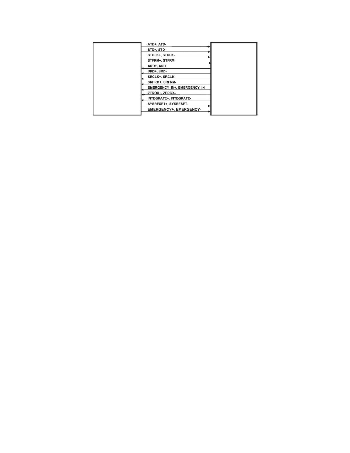
Figure 2-1. PCI Communication Command Board/Distribution Board
Interconnection Diagram
2.3 Distribution Board
The Distribution Board provides interconnections between the Discovery Operator's
Console (PC) and the Scanner. It passes several signal lines from the Operator's Console
and power lines from the DIN rail directly to the C-Arm Interface module. It also provides
buffering and individual drivers and receivers for various signal lines to and from
individual Scanner modules and the PCI Communication Command Board. The
Distribution Board is located in the Electronics Tray in the base of the Scanner.
One cable connects the Operator's Console (PC) communications bus to the Distribution
Board. One cable connects to the Distribution Board from the DIN rail. This cable brings
DC power to the Distribution Board and connects the X-Ray On and Emergency signal
lines to the Power Module.
Up to eight cables connect the Distribution Board to the various Scanner boards
depending on instrument model. Four cables connect to the four Motor Controller Boards
(Table X, Table Y, Arm R, and Arm Y). A single cable connects to the TZ Drive Board.
Two cables (one signal and one power) connect to the C-Arm Interface Board. In addition,
one cable connects to the scanner Control Panel Interface Board. In the C and W models,
this board is a separate section of the Detector Board. In the A and SL versions, the
Control Panel Interface Board is a separate board located under the table.
The Distribution Board has provision for three jumpers that can be installed to override
the EMERGENCY signal lines when troubleshooting.
2.3.1 Power
The Distribution Board receives +24 and +/-15VDC from the Multi-voltage DC Switching
Power Module. The +24VDC is applied through four individual circuit breakers to the
Table X, Table Y, Arm R, and Arm Y Motor Controller Boards. The +24 and +/-15VDC
are passed to the C-Arm Interface Board. The +24 VDC is also reduced to +7 and +5VDC
by regulators to power op-amps and analog switches located on this board. The +7VDC is
passed to the Control Panel Controller Board. The +5VDC powers the digital section of
PCI
Communication
Command
Board
DISTRIBUTION
BOARD