Discovery QDR Series Technical Manual
2-4
the Distribution Board. The +24VDC power supply is not closely regulated and its outputs
may range from +24V to +35V under normal conditions.
Note: +7VDC may measure anywhere from +6.25VDC to +7.25VDC. This is true
everywhere +7VDC is shown in this manual.
Limits for +/- 15VDC
Six green LEDs indicate the status of the +28 (on QDR-4500s, +24 on Discovery), +24,
+15, -15, +7 and +5VDC (ON indicates the respective voltage is present). Five red LEDs
indicate the status of the five circuit breakers applying voltage to the motor drivers/
controller. ON indicates the circuit breaker has been tripped by an over-current condition.
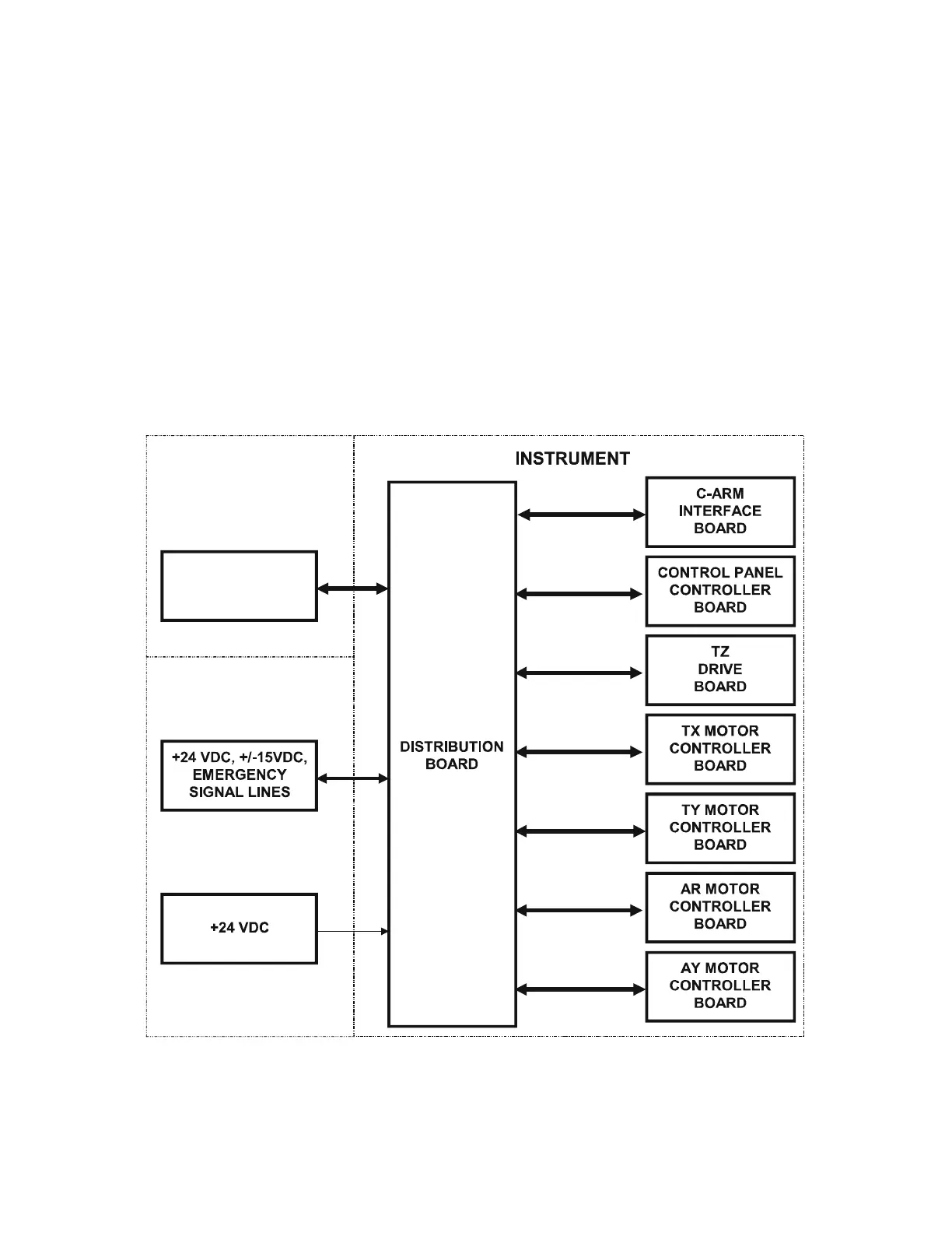
2.3.2 Interface Connections
Figure 2-2 shows connections to/from the Distribution Board.
Figure 2-2. Distribution Board High Level Interconnection Diagram
COMMUNICATIONS
CONTROLLER
BOARD
OPERATOR’S
CONSOLE
COMPUTER
INSTRUMENT
ELECTRONICS
TRAY