Discovery QDR Series Technical Manual
2-25
Each integrator has an additional input into which a test signal (TESTLVL) can be
applied when there are no X-rays present. This test signal is used to verify the operation of
the integrators and multiplexors when running the diagnostic program SQVERIFY.
2.12.1 Power
The Integrator/Multiplexor board receives +/-15V and +5V from the Analog to Digital
board. The +/-15V is passed through this board to the Solid State Detector boards. Voltage
regulators, located on this board, convert this voltage to +/-12V to power circuitry
contained on this board. Analog and digital returns are kept separate.
2.12.2 Interface Connections
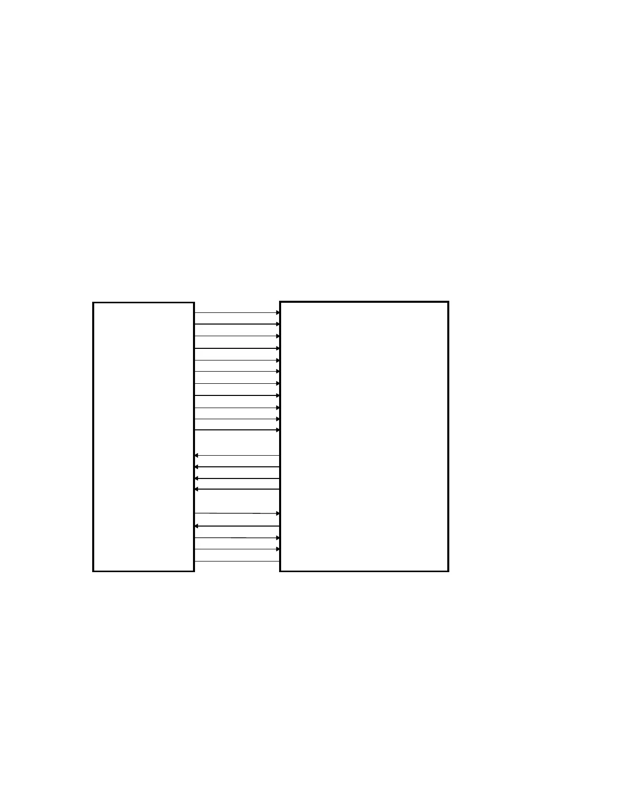
Figure 2-11 shows the interconnections between the Analog/Digital Converter board and
the Integrator/Multiplexor board. Table 2-15 describes the interface signals and identifies
the interconnection connector and pin assignments.
Figure 2-11. Analog Digital Converter Board/Integrator Multiplexor Board
Interconnection Diagram
MA1, MA2
MB1, MB2
MC1, MC2
MD1, MD2
MUX0 - MUX3
MGN1, MGN2
GPL1, GPL2
LTCH1, LTCH2
INTEG
DISC
TSTEN
BB0
BB1
BB2
BB3
+15V
15V_RTN
-15V
+5V
GND
ANALOG/DIGITAL
CONVERTOR
BOARD
INTEGRATOR/MULTIPLEXOR
BOARD