Discovery QDR Series Technical Manual
3-18
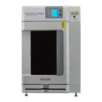
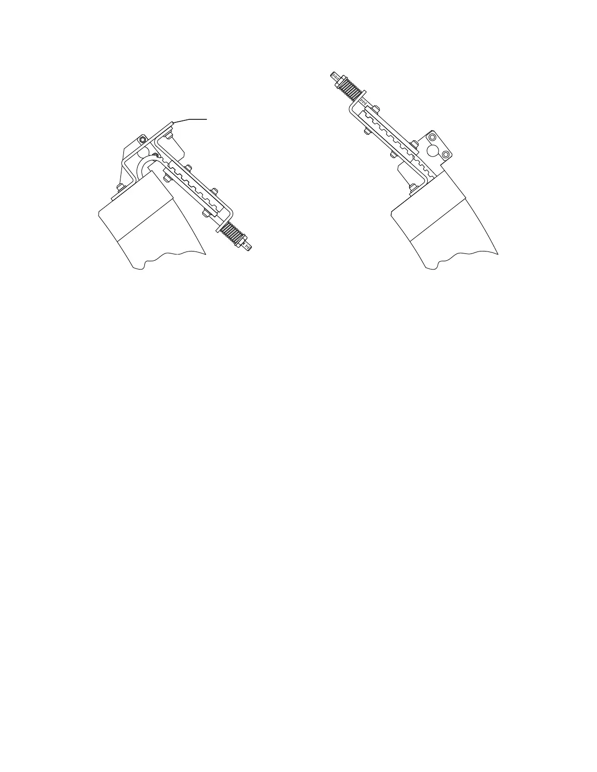
Figure 3-20. Repositioning the Belt Tensioning Mechanism
9. Install the two 1/2" bolts.
10. Remove the C-arm top cover.
11. Install the counter-weights (shipped in carton with casters) into the upper C-arm.
12. Connect the two cables from the upper C-arm to the lower C-arm.
13. Install the 1/2" x 13" trim plate that mounts (on the front) between the upper and
lower C-arm (make sure trim plate is aligned to front of C-Arm).
14. Remove the four C-arm shipping brackets (see Figure 3-20). Save these brack-
ets, they are needed if the tank is ever removed.
15. Level the scanner left to right.
16. Level the system front to back: be sure the scanner table top is level 0° ±0.0°
front to rear at both the head and foot ends. Failure to level A and SL models
will result in TZ, and other, positioning tolerance errors when attempting to
acquire whole body, lateral, or IVA scans.
3.3 Install the System
3.3.1 Install Cables
Follow the procedure below to cable the system:
1. Locate the box shipped with the system containing the Voltage Selection Kit that
includes the AC Input cable, Main Circuit Breaker, jumpers wires, and mounting
hardware.
2. Confirm that you have the proper kit for the site’s AC voltage (100/120/
230VAC).