Discovery QDR Series Technical Manual
2-11
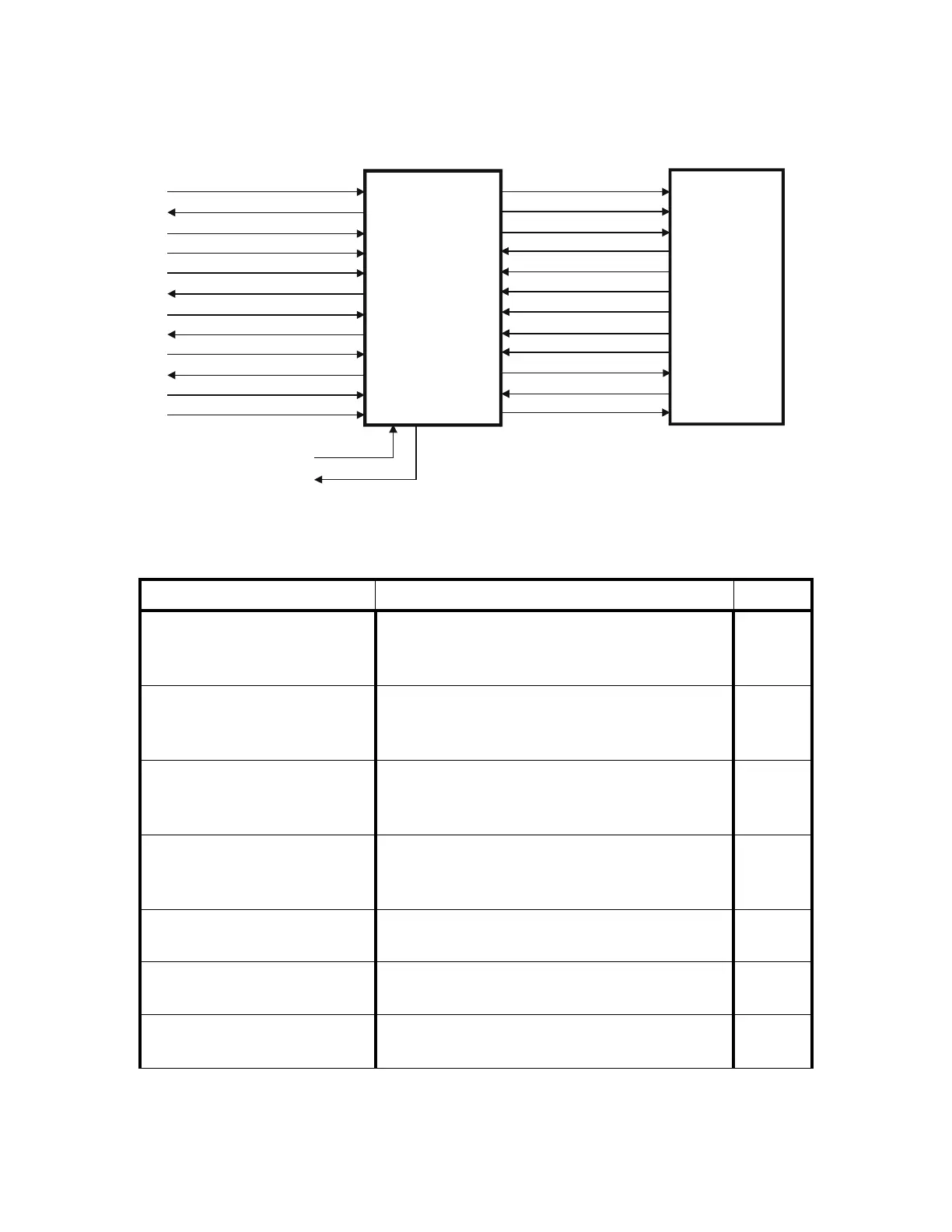
Figure 2-5. Control Panel Controller Interconnection Diagram
Table 2-8. Distribution Board/Control Panel Controller Interconnection Descriptions
Signal Description Pin
ARD+
ARD-
Asynchronous Receive Data from the PCI
Communication Command Board via the
Distribution Board.
JP2-4
JP2-5
ATD+
ATD-
Asynchronous Transmit Data to the PCI
Communication Command Board via the
Distribution Board
JP2-7
JP2-8
SYSRESET+
SYSRESET-
System Reset from the PCI Communication
Command Board via the Distribution Board.
Resets the Control Panel Controller.
JP2-10
JP2-11
EMERGENCY+
EMERGENCY-
Emergency TZ drive indicator from the PCI
Communication Command Board via the
Distribution Board.
JP2-13
JP2-14
XRAY_LIGHT+
XRAY_LIGHT-
X-Ray Light from the X-Ray Controller via
the C-Arm Interface and Distribution Boards.
JP2-16
JP2-17
EMERGENCY_CPANEL
HW_EMERGENCY_RET
State of the STOP switch and of the collision sensor.
(Part of the safety daisy chain.)
JP2-19
JP2-20
+7V DC power for the Control Panel Controller
Board
JP2-2
ARD+, ARD-
ATD+, ATD-
SYSRESET+, SYSRESET-
EMERGENCY+, EMERGENCY-
XRAY_LIGHT+, XRAY_LIGHT-
MAN_TZ_UP
MAN_TZ_UP_RET
MAN_TZ_DOWN
MAN_TZ_DOWN_RET
EMERBENCY_PANEL
HW_EMERGENCY_RET
+7V
L0_PWR* - L7_PWR*
TZ_PWR*
XRAY_LIGHT_PWR*
SW0 - SW2
SR0 - SR2
MAN_TZ_UP
MAN_TZ_UP_RET
MAN_TZ_DOWN
MAN_TZ_DOWN_RET
EMERGENCY_PANEL
HW_EMERGENCY_RET
+5V
PANEL
CONTROLLER
OPERATOR
CONTROL
PANEL
To/From
Distribution Board
TILT_A
TILT_B
To/From
C-Arm
Tilt Switch
(A/SL)