Discovery QDR Series Technical Manual
2-14
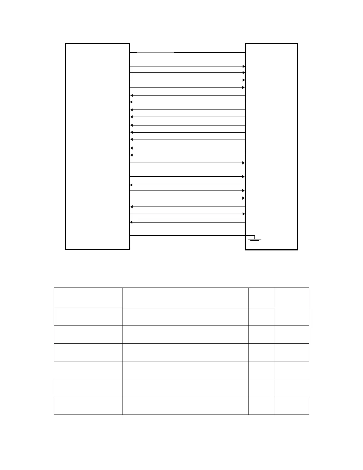
Figure 2-6. Distribution Board/C-Arm Interface Board
Interconnection Diagram
Table 2-10. Distribution Board/C-Arm Interface Board Interconnection Descriptions
Signal Description
Dist
1
Pin
C-ARM
2
Pin
ARD_CARM+
ARD_CARM-
Asynchronous data to the C-Arm Interface Board. JP1-3
JP1-4
JP1-3
JP1-4
STD+
STD-
Synchronous data through the C-Arm Interface
Board to the DAS.
JP1-6
JP1-7
JP1-6
JP1-7
STCLK+
STCLK-
Synchronizes data through the C-Arm Interface
Board to the DAS.
JP1-9
JP1-10
JP1-9
JP1-10
STFRM+
STFRM-
Synchronous channel data frame from PCI Board
through the Distribution Board to the DAS.
JP1-12
JP1-13
JP1-12
JP1-13
ATD_ CA RM +
ATD_ CA RM -
Asynchronous Data from the from the C-Arm
Interface Board.
JP1-15
JP1-16
JP1-15
JP1-16
SRD+
SRD-
Synchronous Data through the C-Arm Interface
Board from the DAS.
JP1-18
JP1-19
JP1-18
JP1-19
ATD_CARM+, ATD_CARM-
STD+, STD-
STCLK+, STCLK-
STFRM+, STFRM-
ARD_CARM+, ARD_CARM-
SRD+, SRD-
SRCLK+, SRCLK-
SRFRM+, SRFRM-
EMERGENCY_CARM, EMERGENCY_CPANEL
LINESYNC+, LINESYNC-
INTEGRATE+, INTEGRATE-
SYSRST_CARM+, SYSRST_CARM-
EMERGENCY+, EMERGENCY-
XRAY_LIGHT+, XRAY_LIGHT-
+15V
15V_RET
-15V
24V
24V_RET
28V
28V_RET
C-ARM
INTERFACE
BOARD
DISTRIBUTION
BOARD
CONTINUITY 1