14 15
INSTALL
INSTALL MANUAL
This step only applies to installs ulizing mulple Stack’d Series
baeries running in parallel. Aer compleng step 4 for each
baery stack and detecng the number of baery modules, it is
now me for the master BMS to detect the number of paralleled
systems running together. Follow the order of operaons below
in careful detail. At this point, all power buons should be
pressed ON and step 4 should be completed for each individual
stack.
a) On all baeries running in parallel (except for the
master baery), set the red invert set DIP switches to
#1 UP, with DIP switches #2-6 DOWN.
b) On the master baery, set the red invert set DIP
switches to #1 DOWN, with DIP switches #2-6 UP.
c) Turn the power buon of the BMS ON, starng with
the furthest paralleled system from the master baery.
Wait 5 seconds. Then turn the next system in parallel
BMS ON and wait 30 seconds. Repeat and nish by
turning ON the master baery’s BMS last.
d) Aer what can take up to 3 minutes, the BMS display
of the master baery will ash the total number of
paralleled systems detected.
If this number is not correct, check that you’ve powered on
all modules and set their DIP switches correctly. Addionally,
check that the DIP switch sengs on all BMS’s in parallel
are correct. Check that communicaons cables are correctly
inserted between Link A to Link B.
4c. PARALLEL ONLY: Parallel Detecon Mode
This step only applies to installs ulizing mulple Stack’d Series
baeries running in parallel. At this point, all power buons
should be pressed OFF.
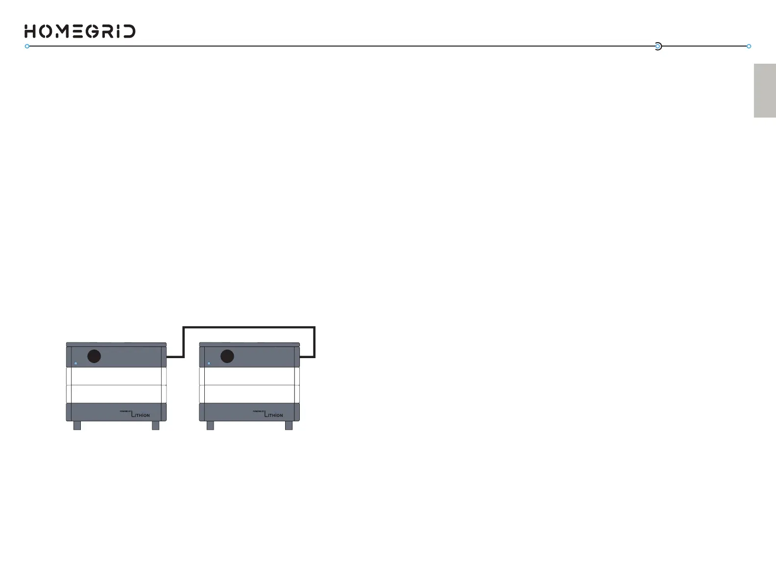
a) Use a standard Ethernet cable to connect the stacks.
There is an extra Ethernet cable included in the
packaging for this purpose.
b) Connect the cable to the “Link A” port of the master
BMS
c) Connect the other end of the cable to “Link B” port of
the paralleled BMS
d) For installs with more systems in parallel, repeat the
paern of Link A to Link B
4b. PARALLEL ONLY: Linking Parallel Stacks with
Communicaon Cables
Power Power
LINK
PORT A
LINK
PORT
B