12 13
INSTALL
INSTALL MANUAL
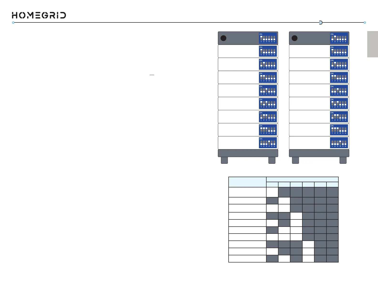
Addr. SET DIP Switch Posions
1 2 3 4 5 6
Master BMS
ON OFF OFF OFF OFF OFF
Stack 2 BMS
OFF ON OFF OFF OFF OFF
Stack 3 BMS
ON ON OFF OFF OFF OFF
Stack 4 BMS
OFF OFF ON OFF OFF OFF
Stack 5 BMS
ON O FF ON OFF OFF OFF
Stack 6 BMS
OFF ON ON OFF OFF OFF
Stack 7 BMS
ON ON ON OFF OFF OFF
Stack 8 BMS
OFF OFF OFF ON OFF OFF
Stack 9 BMS
ON OFF OFF ON OFF OFF
Stack 10 BMS
OFF ON OFF ON OFF OFF
Master
BMS
Module 2 - Switch 2 UP
Module 1 - Switch 1 UP
Module 4 - Switch 3 UP
Module 3 - Switch 1,2 UP
Module 6 - Switch 2,3 UP
Module 5 - Switch 1,3 UP
Module 8 - Switch 4 UP
Module 7 - Switch 1,2,3 UP
- Switch 1 UP
Stack 2
BMS
ON
Module 2 - Switch 2 UP
Module 1 - Switch 1 UP
Module 4 - Switch 3 UP
Module 3 - Switch 1,2 UP
Module 6 - Switch 2,3 UP
Module 5 - Switch 1,3 UP
Module 8 - Switch 4 UP
Module 7 - Switch 1,2,3 UP
- Switch 2 UP
Now, for the BMS of the system, we need to run a detecon of
how many baery modules have been stacked. Follow the order
of operaons below in careful detail.
a) On the BMS, ip the red “invert set” DIP switches all
UP, #1-6 (this puts the BMS in detecon mode).
b) Power ON the baery modules, starng from the
boom baery module to the top. (Aer you power
ON, a green light should appear)
c) Power ON the BMS. The BMS display will show various
informaon as the system boots.
d) Aer what can take up to 3 minutes, the BMS display
will ash the number of baery modules it detected
within the stack (2-8). Wait 30 seconds aer all
modules are detected before proceeding to the next
step.
If this number is not correct, check that you’ve powered on
all modules, and set their DIP switches correctly. Addionally,
check that the DIP switch sengs on the BMS are correct.
4. Power On Sequence + Detecon Mode
4a. PARALLEL ONLY: Seng the “Address Set” DIP Switches
This step only applies to installs ulizing mulple Stack’d Series
baeries running in parallel. As menoned in the last step, the
DIP switches on the modules should be set depending on how
many baery modules are within the stack. Those seng do
not change for the baery modules. Note however, that the
address set DIP switches on the master baery stack are set to
#1 UP, with the rest DOWN (#2-6), while the second baery in
parallel’s address set is according to its posion in parallel (#2 is
UP, while #1 and #3-6 are DOWN).
If you are installing more than two stacks in parallel, use the
chart on page 15 for the address set DIP switches. At this point,
all power buons should be pressed OFF.