10 11
INSTALL
INSTALL MANUAL
Invert. SET
Addr. SET
Imped. SET
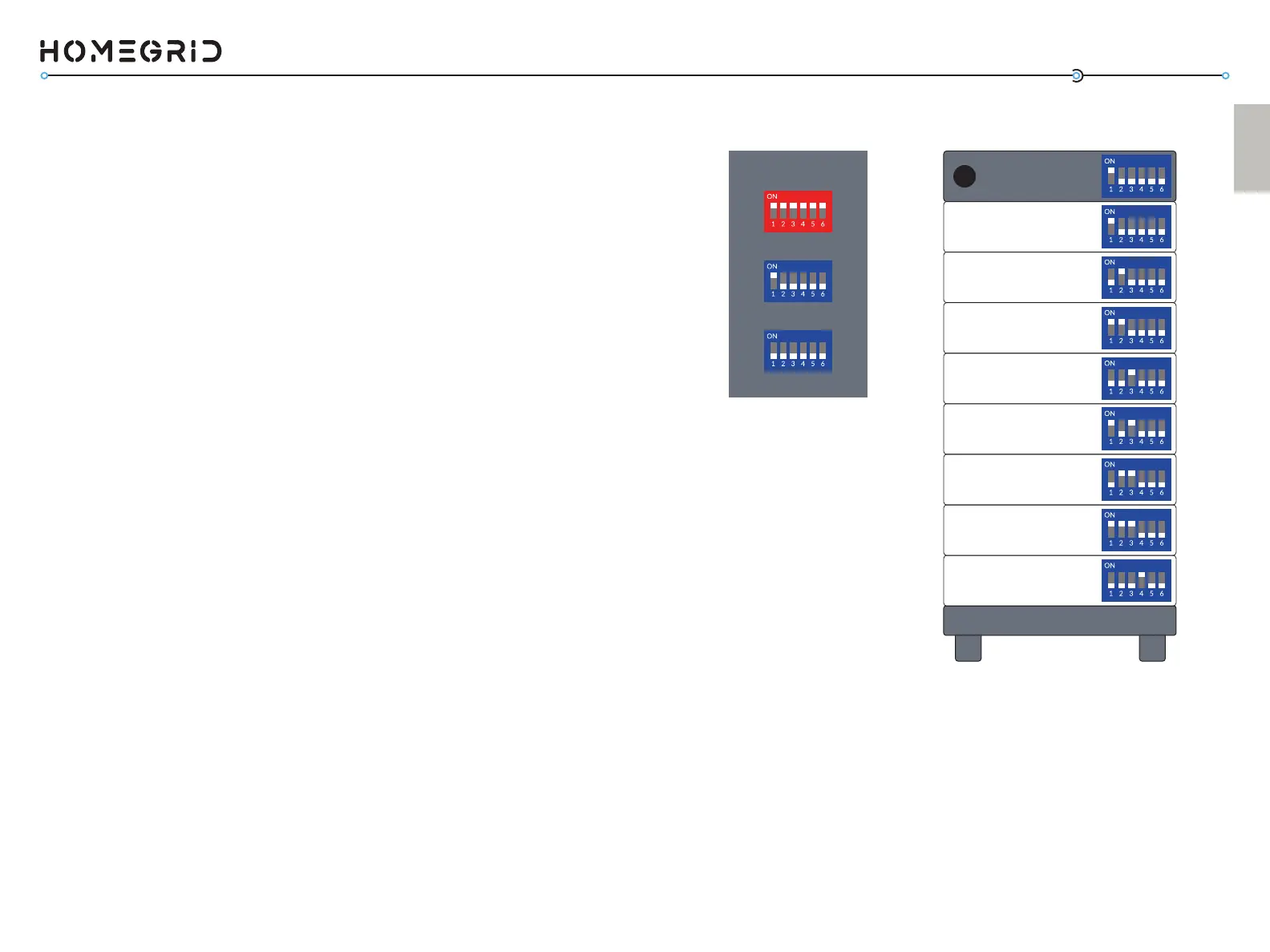
Detecon Mode Address Sengs
Master
BMS
Module 2 - Switch 2 UP
Module 1 - Switch 1 UP
Module 4 - Switch 3 UP
Module 3 - Switch 1,2 UP
Module 6 - Switch 2,3 UP
Module 5 - Switch 1,3 UP
Module 8 - Switch 4 UP
Module 7 - Switch 1,2,3 UP
- Switch 1 UP
Set the Module Address Set DIP Switches
The DIP switch sengs on the baery modules should be set
according to their posion in a stack. For ease of simplicity, we
recommend that you address the rst module beneath the BMS
as baery module #1 and connue downward in this format
unl the last module for your given conguraon. See chart
for recommended numbering sequence and the associated DIP
switch sengs for each module.
The DIP switches on the modules should be set depending on
how many baery modules are within the stack. Ensure that
the baery modules and BMS are not powered on as you are
making these DIP switch changes. Once you have set the DIP
switches to the correct posion for every baery module (see
Address Sengs diagram on page 11) and set the correct DIP
switches on the BMS’s address set (all down, except 1-- see
Detecon Mode diagram on page 11), you can move to step (4).
At this point, all power buons should be pressed OFF.
(Code 56).
• Enabling ‘Connecon Status Mode’ for checking the
‘online status’ (Code 60).
• Enabling ‘Parallel Detecon Mode’ for systems being
congured in parallel (Stacks 2-15).
The DIP switches on the baery modules funcon to:
• Idenfy and orient the module according to its posion
in the stack.