16 17
INSTALL
INSTALL MANUAL
Inverter Communicaon Cable Aachment
a) Run the end of the communicaon cable labeled
“BATTERY” through the smaller compression seal on
the BMS (Master BMS in a parallel install)
b) Plug the communicaon cable into the INV-CAN port
on the baery.
c) The other end of the communicaon cable is labeled
“INVERTER” and connects to the CAN port of the
inverter.
e) Aach the included lugs onto the ends of both posive
and negave 4/0 baery cables (not included) and slide
through the large compression seals. It may be easier to
slide the baery cables through the compression seals
rst and then aach the baery lugs to the baery
cables.
f) Fasten the M8 bolts connecng the baery cable lugs
to the baery terminal busbars using a torque wrench
set to 12 ± 1.2 N.m (106.21 in-lb ± 10.62 in-lb).
g) Reaach the clear plasc covering over the posive and
negave terminals.
h) Screw caps back on the compression seals.
i
The cable provided has had its pins specically
adjusted for a Sol-Ark inverter. If you need to make
your own cable, you must alter the pin sengs
on the inverter end. Please see pg. 29 for wiring
conguraons for other compable inverter COM
cables.
Baery cables may be installed before or aer steps 3-5. In
all cases, ensure that the baery modules and BMS are all
powered OFF. Bus bars, lugs, bolts, and nuts are included in
each BMS box. You must use the provided hardware.
a) Remove the clear plasc covering from over the
posive and negave terminals.
b) Remove all screws (M8 * 16) from each terminal.
c) Aach the included shorter bus bar on the posive
terminals and reaach the screws (M8 * 16) securing it
into place on the BMS.
d) Aach the included longer bus bar on the negave
terminals and reaach the screws (M8 * 16) securing it
into place on the BMS.
6. Cable Installaon + Management
Baery Cable Aachment
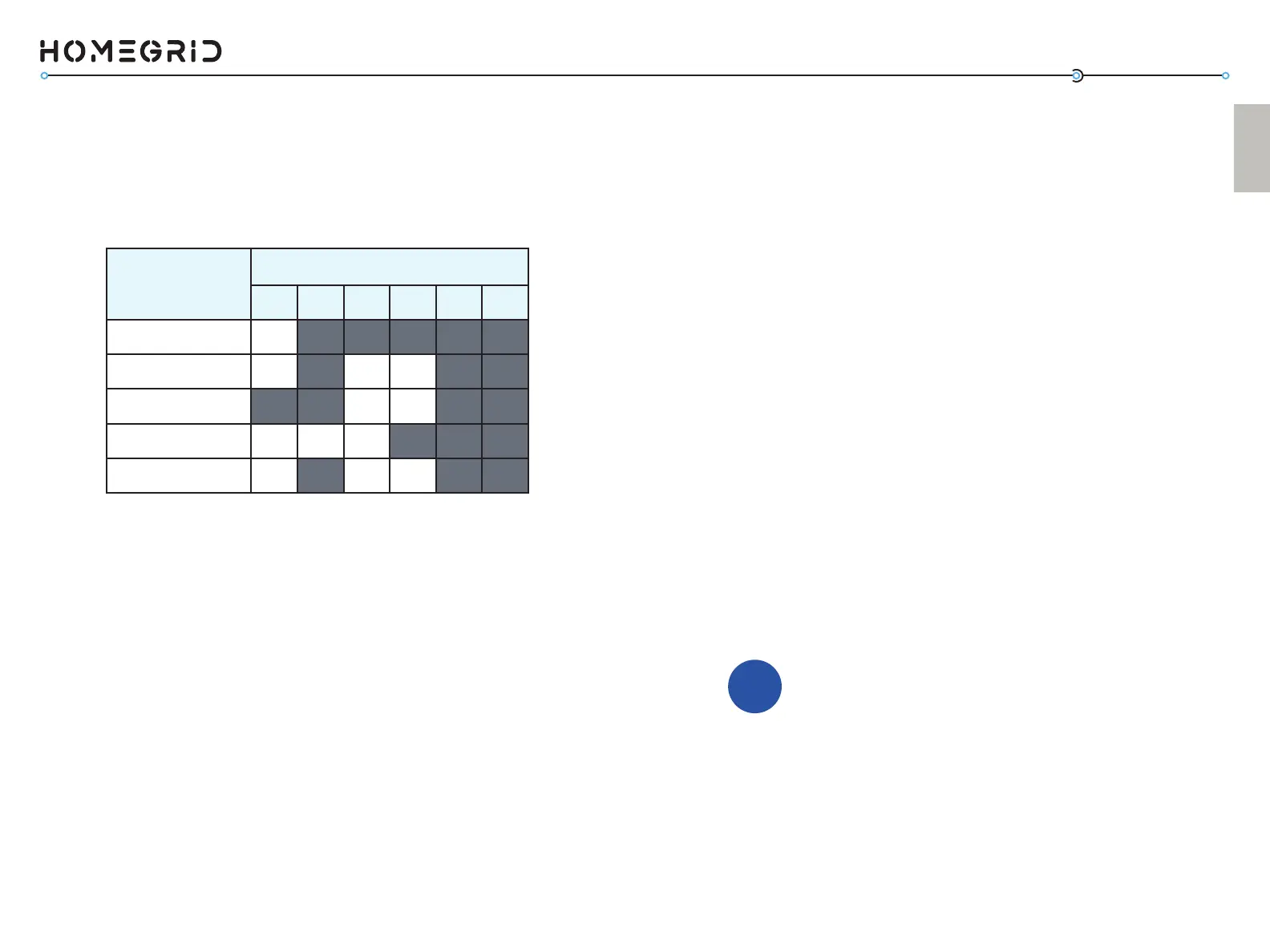
Inverter Brand
DIP Switch Posion (Invert. SET)
1 2 3 4 5 6
Open-Loop
ON OFF OFF OFF OFF OFF
Sol-Ark
ON OFF ON ON OFF OFF
Schneider XW Pro
OFF OFF ON ON OFF OFF
SMA Sunny Island
ON ON ON OFF OFF OFF
LuxPower
ON OFF ON ON OFF OFF
Aer all the baery modules have been successfully recognized
using the “detecon” mode (steps 4 and 4A), change the DIP
switches on the red “Invert set” on the side of the BMS to
match your paired inverter.
5. Set the “Inverter Set” DIP Switches