FRAME/BODY PANELS/EXHAUST SYSTEM
Carrier/Fender Assembly Removal
Procedure
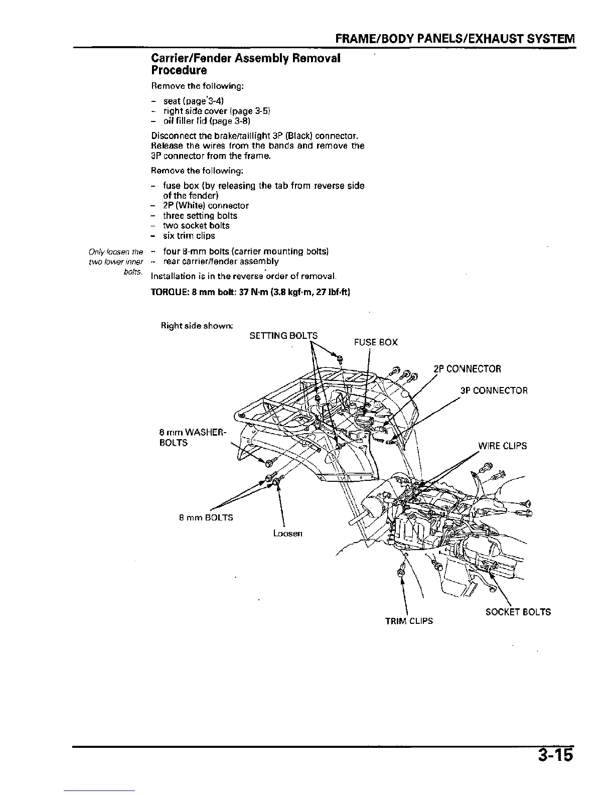
Remove the following:
- seat (page'3-4)
- right side cover (page 3-5)
- oilfiller lid (page 3-8)
Disconnect the brake/taillight 3P (Black) connector.
Release the wires from the bands and remove the
3P connector from the frame.
Remove the following:
- fuse box (by releasing the tab from reverse side
of the fender)
- 2P (White) connector
- three setting bolts
- two socket bolts
- six trim clips
Only loosen
the - four 8-mm bolts (carrier mounting bolts)
two lower
inner
- rear carrier/fender assembly
0 fs
Installation is in the reverse order of removal.
TORQUE: 8 mm bolt: 37 N-m (3.8 kgf-m, 27 Ibfft)
Right side shown:
SETTING BOLTS
FUSE BOX
8 mm WASHER-
BOLTS
2PCONNECTOR
3P CONNECTOR
WIRE CLIPS
8 mm BOLTS
SOCKET BOLTS
TRIM CLIPS
3-15




 To Next Page